THEFT DETERRENT SYSTEM Horn Circuit
DESCRIPTION
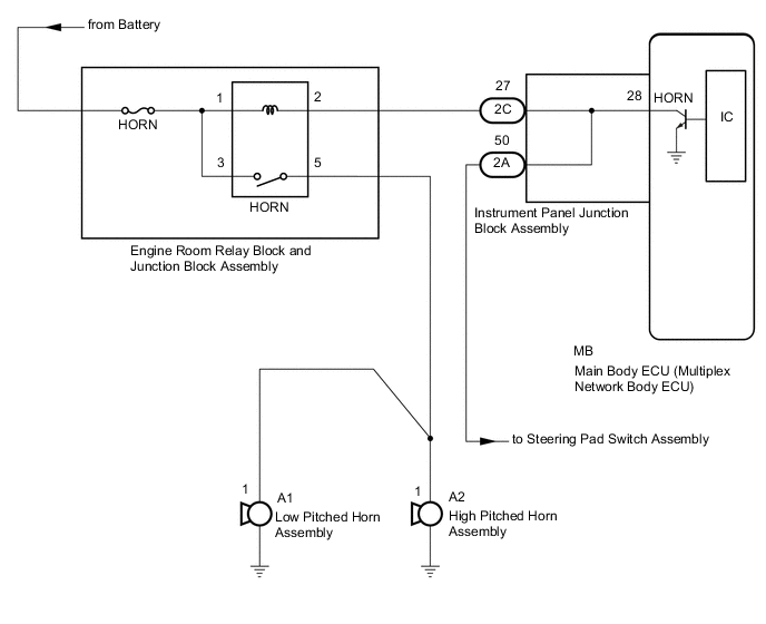
When the theft deterrent system is switched from the armed state to the alarm sounding state, the main body ECU (multiplex network body ECU) transmits a signal to cause the horns to sound at intervals of 0.4 seconds.
WIRING DIAGRAM
CAUTION / NOTICE / HINT
Note
-
Before replacing the main body ECU (multiplex network body ECU), refer to Service Bulletin.
-
Inspect the fuses for circuits related to this system before performing the following procedure.
-
The vehicle battery supplies power to the main body ECU (multiplex network body ECU) via the door control battery. Therefore, before proceeding with troubleshooting, perform an on-vehicle inspection and confirm that the main body ECU (multiplex network body ECU) power source circuit is normal.*
-
*: w/o Canister Pump Module with Door Ajar Warning Buzzer Function
PROCEDURE
-
INSPECT HORNS
-
Press the horn switch and check if the horns sound.
Result Result Proceed to Horns sound A Horns do not sound B
B 
GO TO HORN SYSTEM Click here
A 
-
-
INSPECT INSTRUMENT PANEL JUNCTION BLOCK ASSEMBLY
-
Remove the main body ECU (multiplex network body ECU).
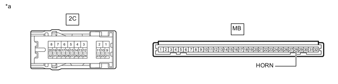
*a Component without harness connected
(Instrument Panel Junction Block Assembly)
- - -
Disconnect the 2C instrument panel junction block assembly connector.
-
Measure the resistance according to the value(s) in the table below.
Standard Resistance Tester Connection Condition Specified Condition 2C-27 - MB-28 (HORN) Always Below 1 Ω Result Proceed to OK NG
OK
REPLACE MAIN BODY ECU (MULTIPLEX NETWORK BODY ECU) Click here
NG
REPLACE INSTRUMENT PANEL JUNCTION BLOCK ASSEMBLY Click here
-