CAN COMMUNICATION SYSTEM Check Bus 4 Lines for Short Circuit
DESCRIPTION
There may be a short circuit between the bus 4 main lines and/or bus 4 branch lines when the resistance between terminals 22 (CA2H) and 7 (CA2L) of the network gateway ECU is below 54 Ω.
| Symptom | Trouble Area |
|---|---|
| Resistance between terminals 22 (CA2H) and 7 (CA2L) of network gateway ECU is below 54 Ω. |
|
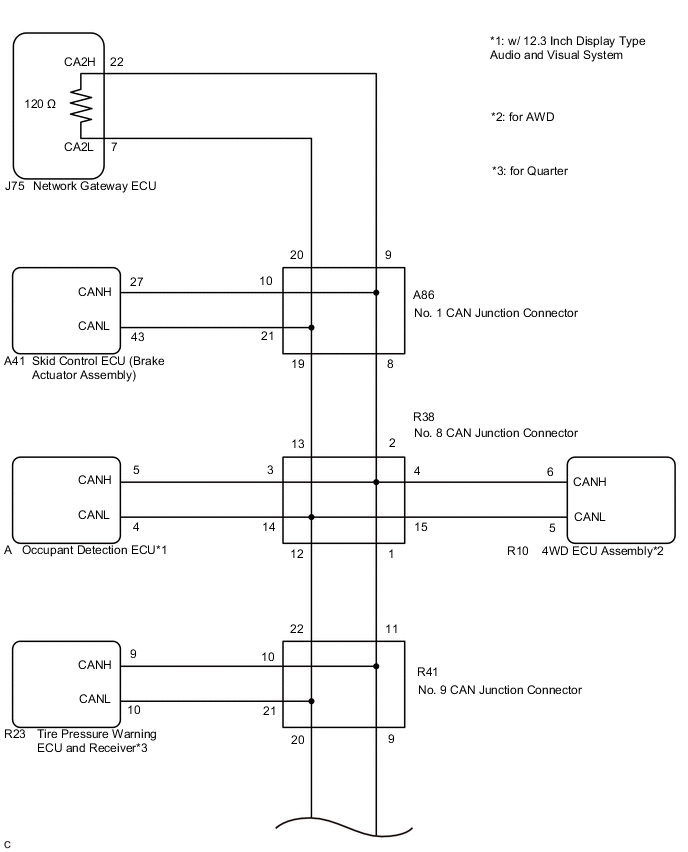
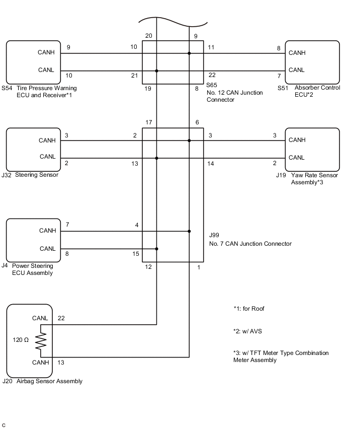
WIRING DIAGRAM
CAUTION / NOTICE / HINT
Note
-
Before measuring the resistance of the CAN bus, turn the engine switch off and leave the vehicle for 1 minute or more without operating the key or any switches, or opening or closing the doors. After that, disconnect the cable from the negative (-) battery terminal and leave the vehicle for 1 minute or more before measuring the resistance.
-
After turning the engine switch off, waiting time may be required before disconnecting the cable from the negative (-) battery terminal. Therefore, make sure to read the disconnecting the cable from the negative (-) battery terminal notices before proceeding with work.
-
Because the order of diagnosis is important to allow correct diagnosis, make sure to begin troubleshooting using How to Proceed with Troubleshooting when CAN communication system related DTCs are output.
-
After performing repairs, perform the DTC check procedure and confirm that the DTCs are not output again.
-
DTC check procedure: Drive the vehicle at a speed of 60 km/h (37 mph) or more for 5 minutes or more.
-
After the repair, perform the CAN bus check and check that all the ECUs and sensors connected to the CAN communication system are displayed.
Tech Tips
-
Operating the engine switch, any other switches or a door triggers related ECU and sensor communication on the CAN. This communication will cause the resistance value to change.
-
Even after DTCs are cleared, if a DTC is stored again after driving the vehicle for a while, the malfunction may be occurring due to vibration of the vehicle. In such a case, wiggling the ECUs or wire harness while performing the inspection below may help determine the cause of the malfunction.
PROCEDURE
-
CHECK FOR SHORT IN CAN BUS LINES (NETWORK GATEWAY ECU)
-
Disconnect the cable from the negative (-) battery terminal.
-
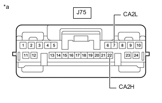
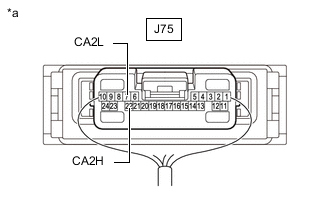
*a Front view of wire harness connector
(to Network Gateway ECU)
Disconnect the J75 network gateway ECU connector.
-
Measure the resistance according to the value(s) in the table below.
Standard Resistance Tester Connection Condition Specified Condition J75-22 (CA2H) - J75-7 (CA2L) Cable disconnected from negative (-) battery terminal 108 to 132 Ω Result Result OK NG
OK 
REPLACE NETWORK GATEWAY ECU Click here
NG 
-
-
CHECK FOR SHORT IN CAN BUS LINES (AIRBAG SENSOR ASSEMBLY)
-
Reconnect the J75 network gateway ECU connector.
-
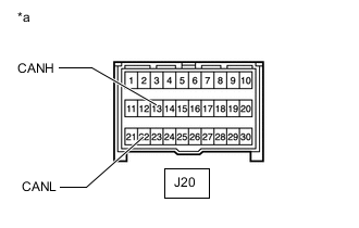
*a Front view of wire harness connector
(to Airbag Sensor Assembly)
Disconnect the J20 airbag sensor assembly connector.
-
Measure the resistance according to the value(s) in the table below.
Standard Resistance Tester Connection Condition Specified Condition J20-13 (CANH) - J20-22 (CANL) Cable disconnected from negative (-) battery terminal 108 to 132 Ω Result Result OK NG
OK
REPLACE AIRBAG SENSOR ASSEMBLY Click here
NG
-
-
CHECK FOR SHORT IN CAN BUS LINES (NO. 9 CAN JUNCTION CONNECTOR)
-
Reconnect the J20 airbag sensor assembly connector.
-
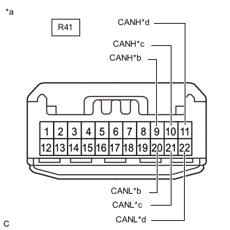
*a Front view of wire harness connector
(to No. 9 CAN Junction Connector)
*b to No. 12 CAN Junction Connector *c to Tire Pressure Warning ECU and Receiver
(for Quarter)
*d to No. 8 CAN Junction Connector Disconnect the R41 No. 9 CAN junction connector.
-
Measure the resistance according to the value(s) in the table below.
Standard Resistance *: for QuarterTester Connection Condition Specified Condition Connected to R41-9 (CANH) - R41-20 (CANL) Cable disconnected from negative (-) battery terminal 108 to 132 Ω No. 12 CAN junction connector R41-10 (CANH) - R41-21 (CANL) Cable disconnected from negative (-) battery terminal 200 Ω or higher Tire pressure warning ECU and receiver* R41-11 (CANH) - R41-22 (CANL) Cable disconnected from negative (-) battery terminal 108 to 132 Ω No. 8 CAN junction connector
Result Result Proceed to OK A NG (No. 8 CAN junction connector) B NG (ECU or sensor branch line) C NG (No. 12 CAN junction connector main line) D
A
REPLACE NO. 9 CAN JUNCTION CONNECTOR
C 
GO TO STEP 8 Click here
D
CHECK FOR SHORT IN CAN BUS LINES (NO. 12 CAN JUNCTION CONNECTOR) Click here
B
-
-
CHECK FOR SHORT IN CAN BUS LINES (NO. 1 CAN JUNCTION CONNECTOR)
-
Reconnect the R41 No. 9 CAN junction connector.
-
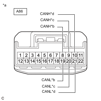
*a Front view of wire harness connector
(to No. 1 CAN Junction Connector)
*b to No. 8 CAN Junction Connector *c to Network Gateway ECU *d to Skid Control ECU (Brake Actuator Assembly) Disconnect the A86 No. 1 CAN junction connector.
-
Measure the resistance according to the value(s) in the table below.
Standard Resistance Tester Connection Condition Specified Condition Connected to A86-8 (CANH) - A86-19 (CANL) Cable disconnected from negative (-) battery terminal 108 to 132 Ω No. 8 CAN junction connector A86-9 (CANH) - A86-20 (CANL) Cable disconnected from negative (-) battery terminal 108 to 132 Ω Network gateway ECU A86-10 (CANH) - A86-21 (CANL) Cable disconnected from negative (-) battery terminal 200 Ω or higher Skid control ECU (brake actuator assembly) Result Result Proceed to OK A NG (Network gateway ECU main line) B NG (ECU or sensor branch line) C NG (No. 8 CAN junction connector main line) D
A
REPLACE NO. 1 CAN JUNCTION CONNECTOR
B
REPAIR OR REPLACE CAN MAIN BUS LINE OR CONNECTOR (NETWORK GATEWAY ECU - NO. 1 CAN JUNCTION CONNECTOR)
C
GO TO STEP 8 Click here
D
-
-
CHECK FOR SHORT IN CAN BUS LINES (NO. 8 CAN JUNCTION CONNECTOR)
-
Reconnect the A86 No. 1 CAN junction connector.
-
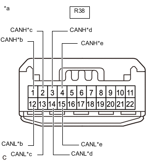
*a Front view of wire harness connector
(to No. 8 CAN Junction Connector)
*b to No. 9 CAN Junction Connector *c to No. 1 CAN Junction Connector *d to Occupant Detection ECU
(w/ 12.3 Inch Display Type Audio and Visual System)
*e to 4WD ECU Assembly
(for AWD)
Disconnect the R38 No. 8 CAN junction connector.
-
Measure the resistance according to the value(s) in the table below.
Standard Resistance *1: w/ 12.3 Inch Display Type Audio and Visual SystemTester Connection Condition Specified Condition Connected to R38-1 (CANH) - R38-12 (CANL) Cable disconnected from negative (-) battery terminal 108 to 132 Ω No. 9 CAN junction connector R38-2 (CANH) - R38-13 (CANL) Cable disconnected from negative (-) battery terminal 108 to 132 Ω No. 1 CAN junction connector R38-3 (CANH) - R38-14 (CANL) Cable disconnected from negative (-) battery terminal 200 Ω or higher Occupant detection ECU*1 R38-4 (CANH) - R38-15 (CANL) Cable disconnected from negative (-) battery terminal 200 Ω or higher 4WD ECU assembly*2
*2: for AWD
Result Result Proceed to OK A NG (No. 1 CAN junction connector main line) B NG (ECU or sensor branch line) C NG (No. 9 CAN junction connector main line) D
A
REPLACE NO. 8 CAN JUNCTION CONNECTOR
B
REPAIR OR REPLACE CAN MAIN BUS LINE OR CONNECTOR (NO. 1 CAN JUNCTION CONNECTOR - NO. 8 CAN JUNCTION CONNECTOR)
C
GO TO STEP 8 Click here
D
REPAIR OR REPLACE CAN MAIN BUS LINE OR CONNECTOR (NO. 8 CAN JUNCTION CONNECTOR - NO. 9 CAN JUNCTION CONNECTOR)
-
-
CHECK FOR SHORT IN CAN BUS LINES (NO. 12 CAN JUNCTION CONNECTOR)
-
Reconnect the R41 No. 9 CAN junction connector.
-
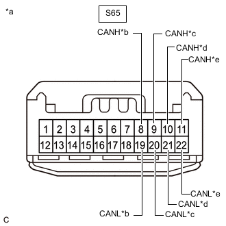
*a Front view of wire harness connector
(to No. 12 CAN Junction Connector)
*b to No. 7 CAN Junction Connector *c to No. 9 CAN Junction Connector *d to Tire Pressure Warning ECU and Receiver
(for Roof)
*e to Absorber Control ECU
(w/ AVS)
Disconnect the S65 No. 12 CAN junction connector.
-
Measure the resistance according to the value(s) in the table below.
Standard Resistance *1: for RoofTester Connection Condition Specified Condition Connected to S65-8 (CANH) - S65-19 (CANL) Cable disconnected from negative (-) battery terminal 108 to 132 Ω No. 7 CAN junction connector S65-9 (CANH) - S65-20 (CANL) Cable disconnected from negative (-) battery terminal 108 to 132 Ω No. 9 CAN junction connector S65-10 (CANH) - S65-21 (CANL) Cable disconnected from negative (-) battery terminal 200 Ω or higher Tire pressure warning ECU and receiver*1 S65-11 (CANH) - S65-22 (CANL) Cable disconnected from negative (-) battery terminal 200 Ω or higher Absorber control ECU*2
*2: w/ AVS
Result Result Proceed to OK A NG (No. 9 CAN junction connector main line) B NG (ECU or sensor branch line) C NG (No. 7 CAN junction connector main line) D
A
REPLACE NO. 12 CAN JUNCTION CONNECTOR
B
REPAIR OR REPLACE CAN MAIN BUS LINE OR CONNECTOR (NO. 9 CAN JUNCTION CONNECTOR - NO. 12 CAN JUNCTION CONNECTOR)
C
GO TO STEP 8 Click here
D
-
-
CHECK FOR SHORT IN CAN BUS LINES (NO. 7 CAN JUNCTION CONNECTOR)
-
Reconnect the S65 No. 12 CAN junction connector.
-
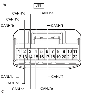
*a Front view of wire harness connector
(to No. 7 CAN Junction Connector)
*b to Airbag Sensor Assembly *c to Steering Sensor *d to Yaw Rate Sensor Assembly
(w/ TFT Meter Type Combination Meter Assembly)
*e to Power Steering ECU Assembly *f to No. 12 CAN Junction Connector Disconnect the J99 No. 7 CAN junction connector.
-
Measure the resistance according to the value(s) in the table below.
Standard Resistance *: w/ TFT Meter Type Combination Meter AssemblyTester Connection Condition Specified Condition Connected to J99-1 (CANH) - J99-12 (CANL) Cable disconnected from negative (-) battery terminal 108 to 132 Ω Airbag sensor assembly J99-2 (CANH) - J99-13 (CANL) Cable disconnected from negative (-) battery terminal 200 Ω or higher Steering sensor J99-3 (CANH) - J99-14 (CANL) Cable disconnected from negative (-) battery terminal 200 Ω or higher Yaw rate sensor assembly* J99-4 (CANH) - J99-15 (CANL) Cable disconnected from negative (-) battery terminal 200 Ω or higher Power steering ECU assembly J99-6 (CANH) - J99-17 (CANL) Cable disconnected from negative (-) battery terminal 108 to 132 Ω No. 12 CAN junction connector
Result Result Proceed to OK A NG (No. 12 CAN junction connector main line) B NG (ECU or sensor branch line) C NG (Airbag sensor assembly main line) D
A
REPLACE NO. 7 CAN JUNCTION CONNECTOR
B
REPAIR OR REPLACE CAN MAIN BUS LINE OR CONNECTOR (NO. 7 CAN JUNCTION CONNECTOR - NO. 12 CAN JUNCTION CONNECTOR)
D
REPAIR OR REPLACE CAN MAIN BUS LINE OR CONNECTOR (AIRBAG SENSOR ASSEMBLY - NO. 7 CAN JUNCTION CONNECTOR)
C
-
-
CHECK FOR SHORT IN CAN BUS LINES (ECU, SENSOR)
-
Reconnect all wire harness connectors.
-
Disconnect the connector that includes terminals CANH and CANL from the ECU or sensor to which the short circuited branch line is connected.
-
*a Component with harness connected
(Network Gateway ECU)
Measure the resistance according to the value(s) in the table below.
Standard Resistance Tester Connection Condition Specified Condition J75-22 (CA2H) - J75-7 (CA2L) Cable disconnected from negative (-) battery terminal 54 to 69 Ω Tech Tips
If the resistance becomes normal (between 54 and 69 Ω) when the connector is disconnected from the ECU or sensor, there may be a short in the ECU or sensor.
Result Result OK NG
OK
REPLACE CORRESPONDING ECU OR SENSOR
NG
REPAIR OR REPLACE CORRESPONDING ECU OR SENSOR BRANCH LINES OR CONNECTOR
-