PANORAMIC VIEW MONITOR SYSTEM ECU Power Source Circuit
DESCRIPTION
This circuit is the power source circuit to operate the parking assist ECU. The parking assist ECU controls the panoramic view monitor system.
WIRING DIAGRAM
-
w/o Stop and Start System
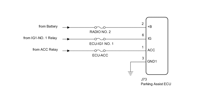
-
w/ Stop and Start System
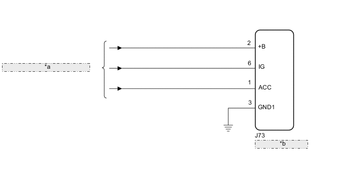
*a from Engine Stop and Start ECU *b Parking Assist ECU
CAUTION / NOTICE / HINT
Note
Inspect the fuse for circuits related to this system before performing the following inspection procedure.
Tech Tips
-
The parking assist ECU is connected to other ECUs via CAN communication or AVC-LAN communication.
-
If the parking assist ECU does not operate due to a power source problem, the audio and visual system*1 or navigation system*2 DTC may be stored due to an AVC-LAN communication interruption.
-
If the parking assist ECU does not operate due to a power source problem, other system DTCs may be stored due to a CAN communication interruption.
-
*1: w/ Audio and Visual System (for 8 Inch Display)
-
*2: w/ Navigation System
PROCEDURE
-
CHECK HARNESS AND CONNECTOR (PARKING ASSIST ECU - BODY GROUND)
-
Disconnect the J73 parking assist ECU connector.
-
Measure the resistance according to the value(s) in the table below.
Standard Resistance Tester Connection Condition Specified Condition J73-3 (GND1) - Body ground Always Below 1 Ω Result Proceed to OK NG
NG 
REPAIR OR REPLACE HARNESS OR CONNECTOR
OK 
-
-
CHECK HARNESS AND CONNECTOR (PARKING ASSIST ECU POWER SSOURCE)
-
Disconnect the J73 parking assist ECU connector.
-
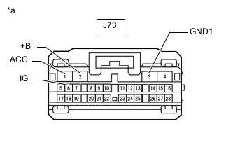
*a Front view of wire harness connector
(to Parking Assist ECU)
Measure the voltage according to the value(s) in the table below.
Standard Voltage Tester Connection Condition Specified Condition J73-2 (+B) - J73-3 (GND1) Always 11 to 14 V*1
10.5 to 16 V*2
J73-1 (ACC) - J73-3 (GND1) Engine switch on (ACC) 11 to 14 V*1
10.5 to 16 V*2
Engine switch off Below 1 V J73-6 (IG) - J73-3 (GND1) Engine switch on (IG) 11 to 14 V*1
10.5 to 16 V*2
Engine switch off Below 1 V
-
*1: w/o Stop and Start System
-
*2: w/ Stop and Start System
Result Result Proceed to OK A NG (w/o Stop and Start System) B NG (w/ Stop and Start System) C -
A
PROCEED TO NEXT SUSPECTED AREA SHOWN IN PROBLEM SYMPTOMS TABLE Click here
B
REPAIR OR REPLACE HARNESS OR CONNECTOR
C
GO TO STOP AND START SYSTEM
-