ULTRASONIC SENSOR(for Rear) REMOVAL

CAUTION / NOTICE / HINT
The necessary procedures (adjustment, calibration, initialization, or registration) that must be performed after parts are removed and installed, or replaced during ultrasonic sensor removal/installation are shown below.
| Replaced Part or Performed Procedure | Necessary Procedure | Effect/Inoperative Function when Necessary Procedure not Performed | Link |
|---|---|---|---|
| Ultrasonic sensor (w/o Intelligent clearance sonar system) | Initialization of ultrasonic sensors | LEXUS parking assist-sensor system (w/o Intelligent clearance sonar system) | |
| Rear bumper assembly or ultrasonic sensor (w/ Intelligent clearance sonar system) |
|
|
PROCEDURE
-
REMOVE REAR BUMPER ASSEMBLY (w/o Rear No. 2 Seat)
-
REMOVE REAR BUMPER ASSEMBLY (w/ Rear No. 2 Seat)
-
REMOVE NO. 3 ULTRASONIC SENSOR (w/o Rear No. 2 Seat)
-
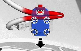

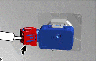
Remove in this Direction Disengage the clamp.
Tech Tips
The illustration is for the LH side. The orientation for the RH side is the opposite of the LH side.
-
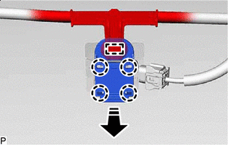
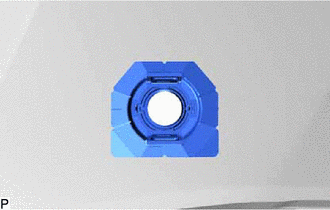
Disengage the 4 claws and remove the ultrasonic sensor clip as shown in the illustration.
-
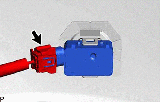
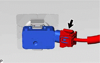
Disconnect the connector.
Tech Tips
The illustration is for the LH side. The orientation for the RH side is the opposite of the LH side.
-
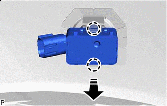
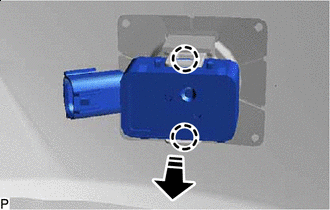
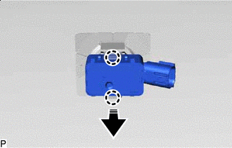
Remove in this Direction Disengage the 2 claws and remove the No. 3 ultrasonic sensor as shown in the illustration.
Tech Tips
The illustration is for the LH side. The orientation for the RH side is the opposite of the LH side.
-
-
REMOVE NO. 3 ULTRASONIC SENSOR (w/ Rear No. 2 Seat)
-
for RH side.
-
Remove in this Direction Disengage the clamp.
-
Disengage the 4 claws and remove the ultrasonic sensor clip as shown in the illustration.
-
-
Disconnect the connector.
Tech Tips
The illustration is for the LH side. The orientation for the RH side is the opposite of the LH side.
-
Remove in this Direction Disengage the 2 claws and remove the No. 3 ultrasonic sensor as shown in the illustration.
Tech Tips
The illustration is for the LH side. The orientation for the RH side is the opposite of the LH side.
-
-
REMOVE NO. 4 ULTRASONIC SENSOR
-
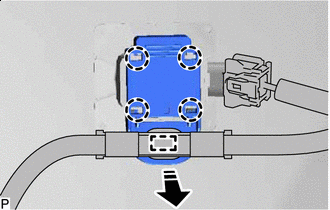
Remove in this Direction Disengage the clamp.
Tech Tips
The illustration is for the LH side.Use the same procedure for the RH side and LH side.
-
Disengage the 4 claws and remove the ultrasonic sensor clip as shown in the illustration.
-
Disconnect the connector.
Tech Tips
The illustration is for the LH side. Use the same procedure for the RH side and LH side.
-
Remove in this Direction Disengage the 2 claws and remove the No. 4 ultrasonic sensor as shown in the illustration.
Tech Tips
The illustration is for the LH side. Use the same procedure for the RH side and LH side.
-
-
REMOVE NO. 3 ULTRASONIC SENSOR RETAINER (w/o Rear No. 2 Seat)
Tech Tips
-
Perform this procedure only when replacement of the No. 3 ultrasonic sensor retainer is necessary.
-
When removing the No. 3 ultrasonic sensor retainer, heat the rear bumper assembly and No. 3 ultrasonic sensor retainer using a heat light.
-
Use the same procedure for all No. 3 ultrasonic sensor retainers.
-
Heat the rear bumper assembly and No. 3 ultrasonic sensor retainer using a heat light at the specified temperature for 3 to 5 minutes.
Heating Temperature Item Temperature Rear Bumper Assembly 40 to 60°C (104 to 140°F) No. 3 Ultrasonic Sensor Retainer CAUTION:
-
Do not touch the heat light and heated parts.
-
Touching the heat light may result in burns.
-
Touching heated parts for a long time may result in burns.
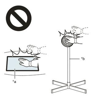
*a Heated Part *b Heat Light -
-
Remove the No. 3 ultrasonic sensor retainer.
-
-
REMOVE NO. 3 ULTRASONIC SENSOR RETAINER (w/ Rear No. 2 Seat)
Tech Tips
-
Perform this procedure only when replacement of the No. 3 ultrasonic sensor retainer is necessary.
-
When removing the No. 3 ultrasonic sensor retainer, heat the rear bumper assembly and No. 3 ultrasonic sensor retainer using a heat light.
-
Use the same procedure for all No. 3 ultrasonic sensor retainers.
-
Heat the rear bumper assembly and No. 3 ultrasonic sensor retainer using a heat light at the specified temperature for 3 to 5 minutes.
Heating Temperature Item Temperature Rear Bumper Assembly 40 to 60°C (104 to 140°F) No. 3 Ultrasonic Sensor Retainer CAUTION:
-
Do not touch the heat light and heated parts.
-
Touching the heat light may result in burns.
-
Touching heated parts for a long time may result in burns.
*a Heated Part *b Heat Light -
-
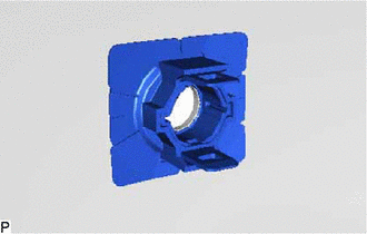
Remove the No. 3 ultrasonic sensor retainer.
-
-
REMOVE NO. 4 ULTRASONIC SENSOR RETAINER
Tech Tips
-
Perform this procedure only when replacement of the No. 4 ultrasonic sensor retainer is necessary.
-
When removing the No. 4 ultrasonic sensor retainer, heat the rear bumper assembly and No. 4 ultrasonic sensor retainer using a heat light.
-
Use the same procedure for all No. 4 ultrasonic sensor retainers.
-
Heat the rear bumper assembly and No. 4 ultrasonic sensor retainer using a heat light at the specified temperature for 3 to 5 minutes.
Heating Temperature Item Temperature Rear Bumper Assembly 40 to 60°C (104 to 140°F) No. 4 Ultrasonic Sensor Retainer CAUTION:
-
Do not touch the heat light and heated parts.
-
Touching the heat light may result in burns.
-
Touching heated parts for a long time may result in burns.
*a Heated Part *b Heat Light -
-
Remove the No. 4 ultrasonic sensor retainer.
-