CLEARANCE WARNING ECU(for RHD) INSTALLATION

PROCEDURE
-
INSTALL CLEARANCE WARNING ECU ASSEMBLY
-
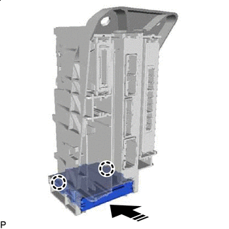

Install in this Direction Engage the 2 claws to install the clearance warning ECU assembly as shown in the illustration.
-
-
INSTALL ECU INTEGRATION BOX LH
-
Install the ECU integration box LH with the bolt and 2 nuts.
- Torque:
- Nut
- 8.0 N*m { 82 kgf*cm, 71 in.*lbf }
-
Connect each connector.
-
Engage the claw.
-
-
INSTALL GLOVE COMPARTMENT DOOR ASSEMBLY
-
INSTALL NO. 2 INSTRUMENT PANEL UNDER COVER SUB-ASSEMBLY
-
INSTALL COWL SIDE TRIM BOARD LH
-
INSTALL FRONT DOOR SCUFF PLATE LH
-
INSTALL INSTRUMENT PANEL GARNISH LH
-
INSTALL LOWER NO. 1 INSTRUMENT PANEL FINISH PANEL
-
CONNECT CABLE TO NEGATIVE BATTERY TERMINAL
Note
When disconnecting the cable, some systems need to be initialized after the cable is reconnected.
-
PERFORM CALIBRATION (w/o Intelligent Clearance Sonar System)
-
PERFORM CALIBRATION (w/ Intelligent Clearance Sonar System)
- SST
- 09989-00020