ROOF HEADLINING(w/o Rear No. 2 Seat) REASSEMBLY
PROCEDURE
-
INSTALL NO. 2 ROOF SILENCER PAD
-
Remove the release paper from 2 new No. 2 roof silencer pads.
Tech Tips
After removing the release paper, keep the exposed adhesive free from foreign matter.
-
Align the 2 No. 2 roof silencer pads with the markings on the roof headlining assembly and install them as shown in the illustration.
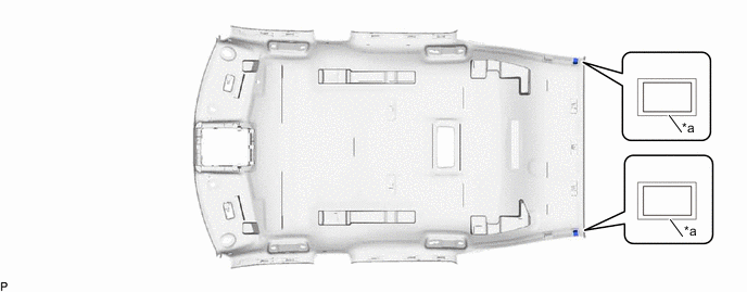
*a Marking - -
-
-
INSTALL NO. 1 ROOF SILENCER PAD
-
Remove the release paper from 2 new No. 1 roof silencer pads.
Tech Tips
After removing the release paper, keep the exposed adhesive free from foreign matter.
-
Align the 2 No. 1 roof silencer pads with the markings on the roof headlining assembly and install them as shown in the illustration.
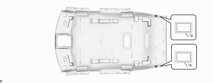
*a Marking - -
-
-
INSTALL NO. 1 ROOF WIRE
-
When using a new roof headlining assembly:
-
for LHD:
-
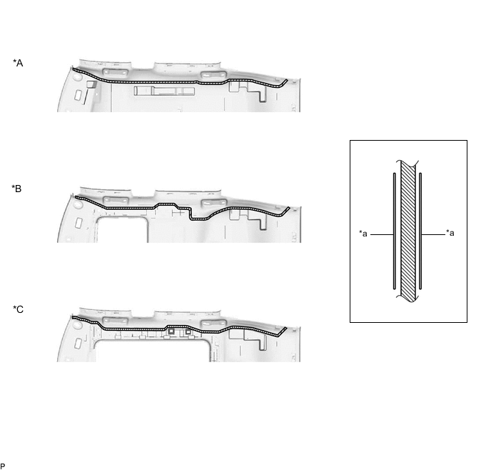
Using a knife, cut the roof headlining assembly at the markings as shown in the illustration.
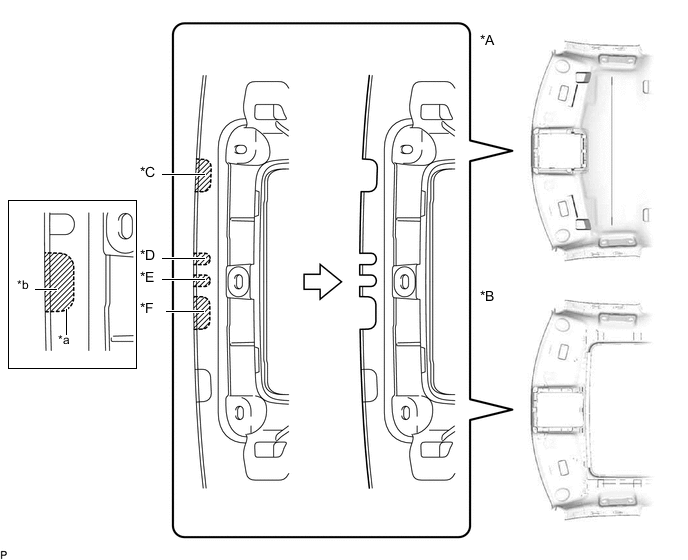
*A for Standard Roof *B except Standard Roof *C w/ Rain Sensor *D w/ EC Mirror with LEXUS Safety System+ *E w/ EC Mirror without LEXUS Safety System+ *F w/ LEXUS Safety System+ *a Marking *b Cut
-
-
for RHD:
-
Using a knife, cut the roof headlining assembly at the markings as shown in the illustration.
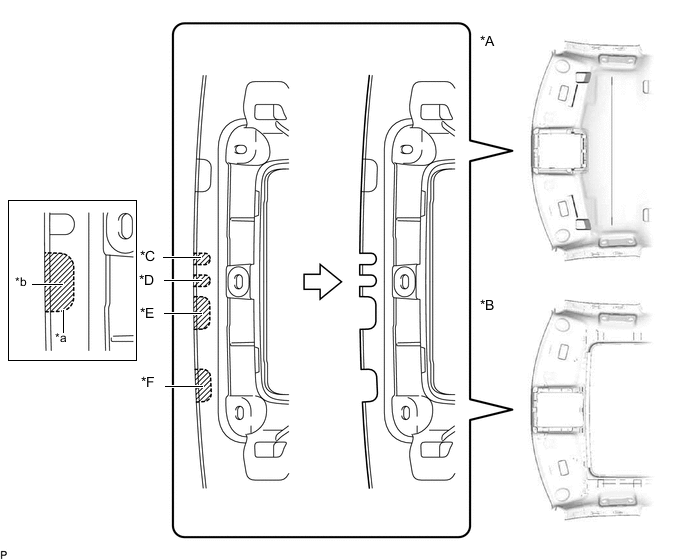
*A for Standard Roof *B except Standard Roof *C w/ EC Mirror with LEXUS Safety System+ *D w/ EC Mirror without LEXUS Safety System+ *E w/ LEXUS Safety System+ *F w/ Rain Sensor *a Marking *b Cut
-
-
-
Apply butyl tape as shown in the illustration.
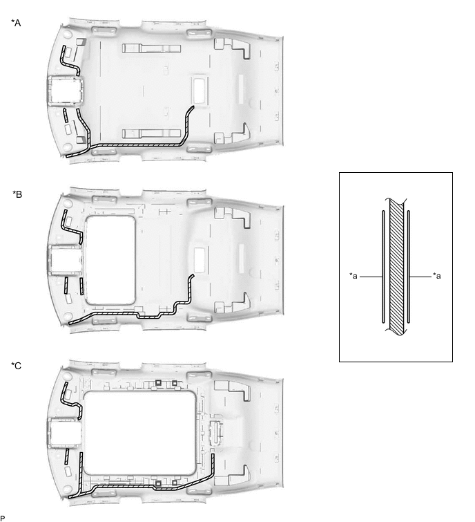
*A for Standard Roof *B for Sliding Roof *C for Panoramic Moon Roof - - *a Marking - - 
Butyl Tape - - Note
Securely attach the butyl tape.
-
Turn the 2 visor connectors clockwise approximately 90° to install them to the roof headlining assembly.
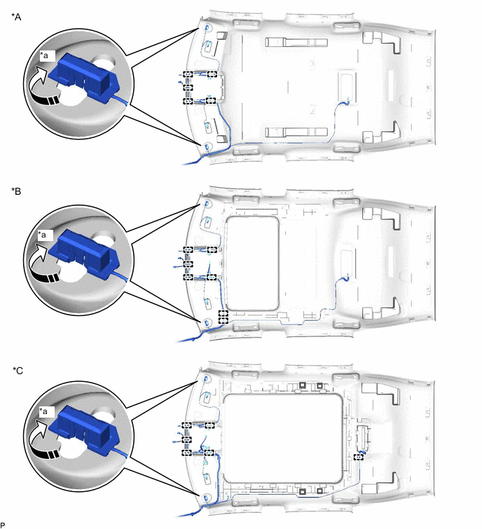
*A for Standard Roof *B for Sliding Roof *C for Panoramic Moon Roof - - *a 90° - - 
Rotation Direction - - -
Engage each clamp.
-
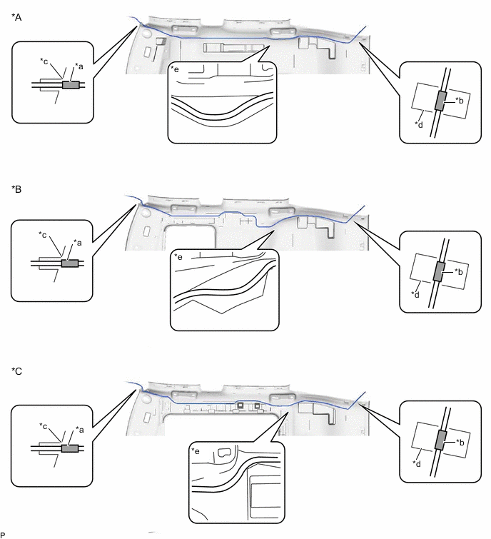
Align the marking tape (A) on the No. 1 roof wire with the vehicle front side tab of the roof headlining assembly.
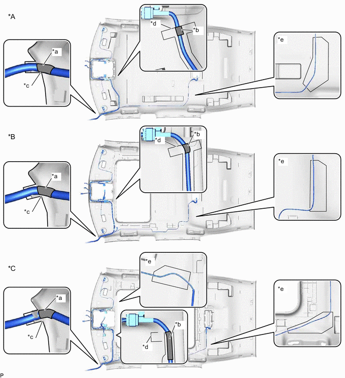
*A for Standard Roof *B for Sliding Roof *C for Panoramic Moon Roof - - *a Marking Tape (A) *b Marking Tape (B) *c Vehicle Front Side Tab of the Roof Headlining Assembly *d Marking *e Adjustment Area - - -
Align the edge of the marking tape (B) on the No. 1 roof wire with the markings on the roof headlining assembly.
-
Attach the No. 1 roof wire with the butyl tape.
Note
-
Securely attach the No. 1 roof wire.
-
If any of the No. 1 roof wire is left loose, it will cause an abnormal noise.
-
Make sure to attach the No. 1 roof wire without leaving any of it loose.
Tech Tips
Secure the extra length of the No. 1 roof wire in the adjustment area.
-
-
Align the edge of the marking tape (C) on the No. 1 roof wire with the markings on the roof headlining assembly.
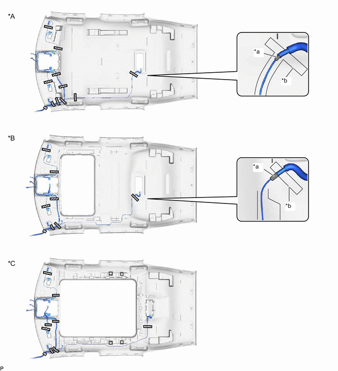
*A for Standard Roof *B for Sliding Roof *C for Panoramic Moon Roof - - *a Marking Tape (C) *b Marking Adhesive Tape - - -
Install the No. 1 roof wire to the roof headlining assembly with adhesive tape.
Note
-
Apply the tape securely in place.
-
Do not touch the adhesive surface when applying the tape to prevent adhesion failure.
-
-
-
INSTALL TELEPHONE MICROPHONE ASSEMBLY
-
INSTALL VANITY LIGHT ASSEMBLY
Tech Tips
Use the same procedure for the RH side and LH side.
-
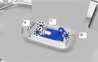
*1 Bulb Holder *a Claw (A) *b Claw (B) Engage the claw (B) to install the vanity light assembly.
-
Engage the 2 claws (A) to install the bulb holder to the vanity light assembly.
-
-
INSTALL WASHER HOSE ASSEMBLY
-
Apply butyl tape as shown in the illustration.
*A for Standard Roof *B for Sliding Roof *C for Panoramic Moon Roof - - *a Marking - - Butyl Tape - - Note
Securely attach the butyl tape.
-
Align the marking tape (A) on the washer hose assembly with the vehicle front side tab of the roof headlining assembly.
*A for Standard Roof *B for Sliding Roof *C for Panoramic Moon Roof - - *a Marking Tape (A) *b Marking Tape (B) *c Vehicle Front Side Tab of the Roof Headlining Assembly *d Marking *e Adjustment Area - - -
Align the edge of the marking tape (B) on the washer hose assembly with the markings on the roof headlining assembly.
-
Attach the washer hose assembly with the butyl tape.
Note
-
Securely attach the washer hose assembly.
-
If any of the washer hose assembly is left loose, it will cause an abnormal noise.
-
Make sure to attach the washer hose assembly without leaving any of it loose.
Tech Tips
Secure the extra length of the washer hose assembly in the adjustment area.
-
-
-
INSTALL NO. 2 ANTENNA CORD SUB-ASSEMBLY