FRONT CONSOLE BOX REMOVAL
PROCEDURE
-
REMOVE REMOTE TOUCH ASSEMBLY
-
REMOVE LOWER NO. 2 INSTRUMENT PANEL FINISH PANEL
-
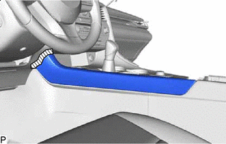

Protective Tape Apply protective tape to the area shown in the illustration.
-
Disengage the 7 clips to remove the lower No. 2 instrument panel finish panel as shown in the illustration.
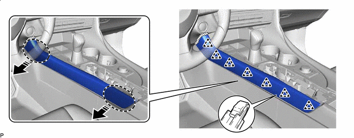

Place Hand Here 
Remove in this Direction
-
-
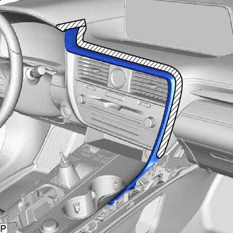
REMOVE LOWER NO. 1 INSTRUMENT PANEL FINISH PANEL
Note
Make sure to perform this procedure carefully, otherwise the lower No. 1 instrument panel finish panel may be damaged.
-
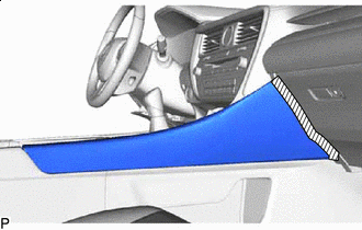
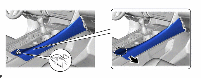
Protective Tape Apply protective tape to the area shown in the illustration.
-
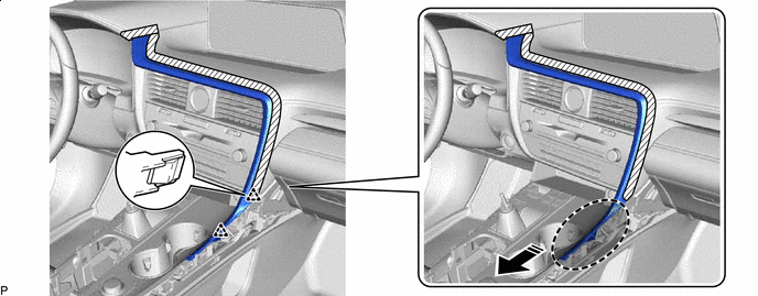
Disengage the 2 clips as shown in the illustration.
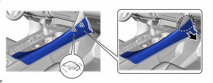
Place Hand Here Remove in this Direction -
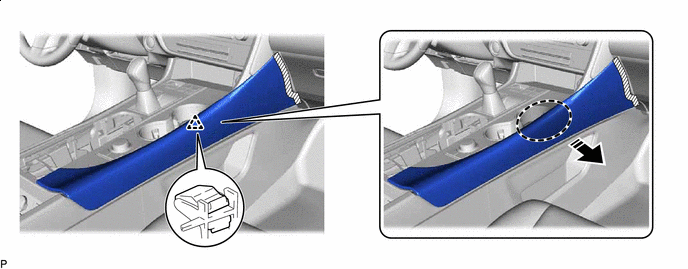
Disengage the clip as shown in the illustration.
Place Hand Here Remove in this Direction -
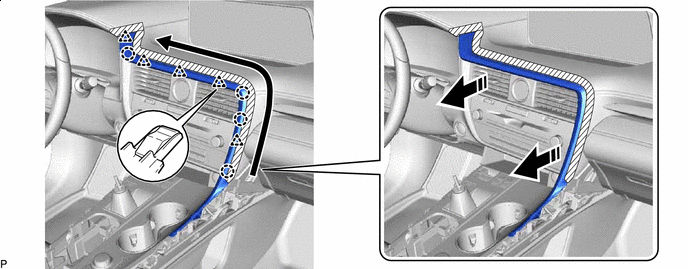
Disengage the clip as shown in the illustration.
Place Hand Here Remove in this Direction -
Disengage the 4 clips to remove the lower No. 1 instrument panel finish panel as shown in the illustration.
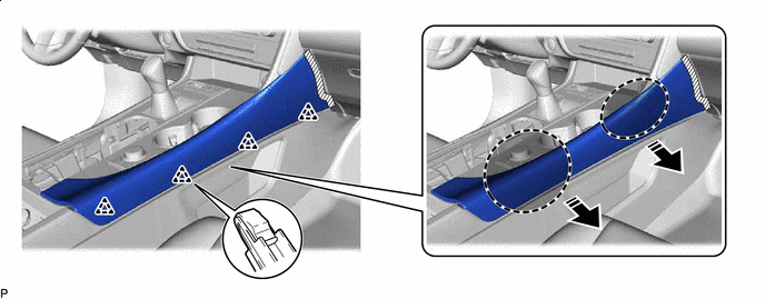
Place Hand Here Remove in this Direction
-
-
REMOVE SHIFT LEVER KNOB SUB-ASSEMBLY
-
Remove in this Direction Disengage the claw and disconnect the shift hole cover sub-assembly as shown in the illustration.
-
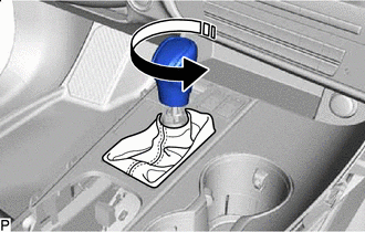
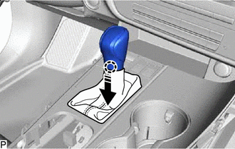
Remove in this Direction Turn the shift lever knob sub-assembly counterclockwise and remove it.
-
-
REMOVE INSTRUMENT CLUSTER FINISH PANEL ORNAMENT
-
Protective Tape Apply protective tape to the areas shown in the illustration.
-
Disengage the 2 clips as shown in the illustration.
Place Hand Here Remove in this Direction -
Disengage the 4 claws and 5 clips to remove the instrument cluster finish panel ornament as shown in the illustration.
Remove in this Direction 
Order of Removal
-
-
REMOVE CONSOLE PANEL SUB-ASSEMBLY
-
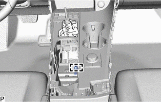
Disengage the clamp.
-
Move the shift lever to N.
-
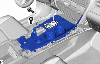
Remove the 2 screws.
-
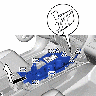
Remove in this Direction Disengage the 4 clips and 5 guides as shown in the illustration.
-
Disconnect each connector to remove the console panel sub-assembly.
-
-
REMOVE INSTRUMENT PANEL CUP HOLDER ASSEMBLY
-
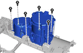
Remove the 6 screws and instrument panel cup holder assembly.
-
-
REMOVE MAYDAY BATTERY WITH BRACKET (w/ Telematics Transceiver)
-
REMOVE CONSOLE REAR END PANEL SUB-ASSEMBLY
-
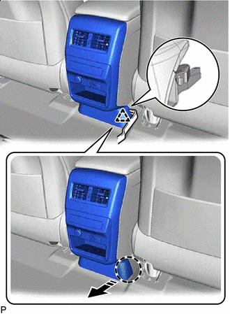
Insert Moulding Remover B Here Remove in this Direction Using a moulding remover B, disengage the clip as shown in the illustration.
-
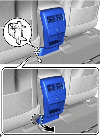
Insert Moulding Remover B Here Remove in this Direction Using a moulding remover B, disengage the clip as shown in the illustration.
-
Disengage the 4 clips and 4 claws as shown in the illustration.
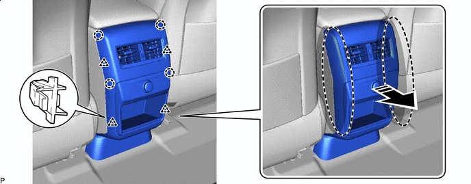
Place Hand Here Remove in this Direction -
Disconnect each connector.
-
w/ Rear Seat Entertainment System:
-
Disengage the 3 claws.
-
-
Remove the console rear end panel sub-assembly.
-
-
REMOVE CONSOLE BOX ASSEMBLY
-
w/o Telematics Transceiver:
-
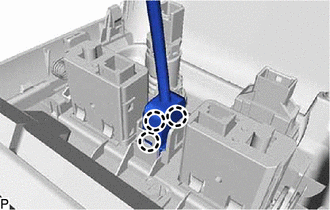
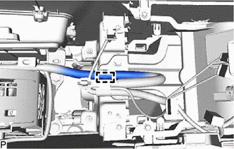
Disengage the clamp.
-
-
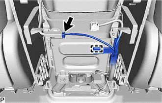
Disengage the clamp.
-
Disconnect the connector.
-
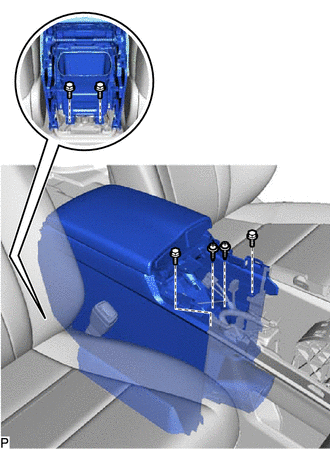
Remove the 4 bolts and 2 screws.
-
Disconnect each connector.
-
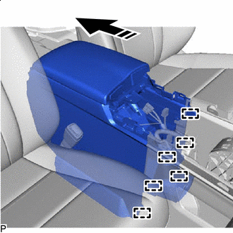
Remove in this Direction Pull the console box assembly as shown in the illustration to disengage the 6 guides and remove the console box assembly.
-