INSTRUMENT PANEL SAFETY PAD REASSEMBLY
PROCEDURE
-
INSTALL GLOVE COMPARTMENT DOOR LOCK CYLINDER ASSEMBLY
-
With the cylinder lock pressed, insert the glove compartment door lock cylinder assembly into the glove compartment door assembly to install it as shown in the illustration.
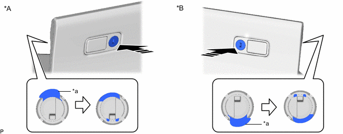
*A for LHD *B for RHD *a Cylinder Lock - - 
Install in this Direction - - -
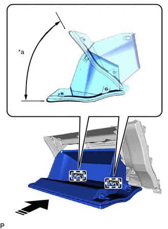
*a 52.5° Install in this Direction With the glove compartment door assembly opened approximately 52.5° from its closed position, engage the 2 hinges horizontally.
Note
Engaging the hinges from an upward angle will deform the hinges. Be sure to install the glove compartment door assembly horizontally.
-
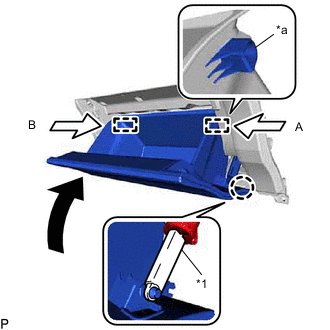
*1 Glove Compartment Door Stopper Sub-assembly *a Stopper Slightly bend the stoppers (A) and (B) in the directions indicated by the arrows shown in the illustration and engage the stoppers to install the glove compartment door assembly.
-
Engage the claw to connect the glove compartment door stopper sub-assembly.
-
-
INSTALL NO. 1 INSTRUMENT PANEL PIN
-
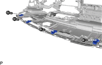
Install the 4 No. 1 instrument panel pins with the 4 screws <D> or <E>.
-
-
INSTALL NO. 2 SIDE DEFROSTER NOZZLE
-
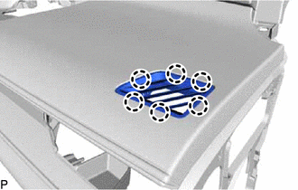
Engage the 6 claws to install the No. 2 side defroster nozzle.
-
-
INSTALL NO. 1 SIDE DEFROSTER NOZZLE
-
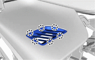
Engage the 6 claws to install the No. 1 side defroster nozzle.
-
-
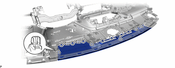
INSTALL NO. 2 INSTRUMENT PANEL WIRE
-
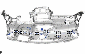
Engage the 10 clamps to install the No. 2 instrument panel wire.
-
-
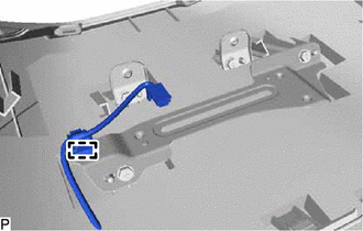
INSTALL ANTENNA CORD SUB-ASSEMBLY
-
INSTALL NO. 1 DEFROSTER NOZZLE GARNISH
-
Engage the 7 guides.
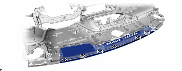
-
Engage the 2 guides, 5 clips and 7 claws to install the No. 1 defroster nozzle garnish.
-
-
INSTALL AUTOMATIC LIGHT CONTROL SENSOR
-
INSTALL NO. 1 METER HOOD RETAINER
-
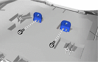
Install the 2 No. 1 meter hood retainers with the 2 screws <D>.
-
-
INSTALL NO. 1 ION GENERATOR BRACKET (w/ Ion Generator)
-
for LHD:
-
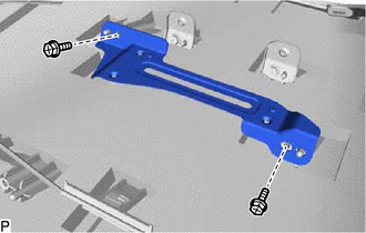
Install the No. 1 ion generator bracket with the 2 screws <D>.
-
-
for RHD:
-
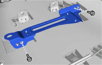
Install the No. 1 ion generator bracket with the 2 screws <D>.
-
Engage the clamp.
-
-
-
INSTALL NO. 2 INSTRUMENT PANEL REGISTER ASSEMBLY
-
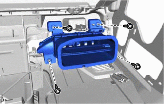
Install the No. 2 instrument panel register assembly with the 4 screws <D>.
-
-
INSTALL NAVIGATION ANTENNA ASSEMBLY WITH BRACKET (w/ Navigation Antenna)
-
INSTALL ION GENERATOR SUB-ASSEMBLY (w/ Ion Generator)
-
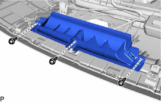
INSTALL NO. 2 SIDE DEFROSTER NOZZLE DUCT
-
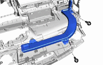
Install the No. 2 side defroster nozzle duct with the 2 screws <D> or <F>.
-
-
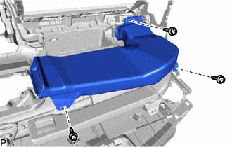
INSTALL NO. 1 SIDE DEFROSTER NOZZLE DUCT
-
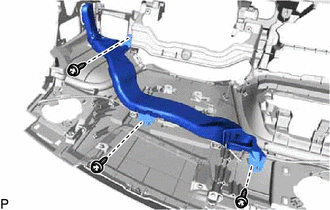
Install the No. 1 side defroster nozzle duct with the 3 screws <D> or <F>.
-
-
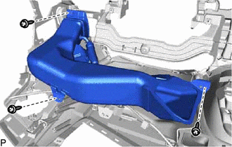
INSTALL DEFROSTER NOZZLE ASSEMBLY
-
Install the defroster nozzle assembly with the 3 screws <D> or <F>.
-
-
INSTALL NO. 4 HEATER TO REGISTER DUCT
-
Install the No. 4 heater to register duct with the 3 screws <D> or <F>.
-
-
INSTALL NO. 1 HEATER TO REGISTER DUCT
-
w/ Ion Generator:
-
Engage the No. 1 heater to register duct assembly to the ion generator sub-assembly.
-
-
Install the No. 1 heater to register duct with the 3 screws <D> or <F>.
-
-
INSTALL INSTRUMENT PANEL PASSENGER AIRBAG ASSEMBLY
-
INSTALL HEADUP DISPLAY (METER MIRROR SUB-ASSEMBLY) (w/ Headup Display)