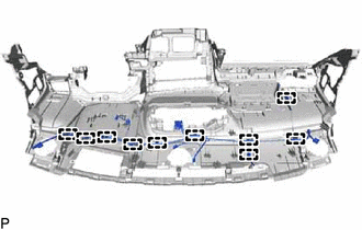
INSTRUMENT PANEL SAFETY PAD DISASSEMBLY
PROCEDURE
-
REMOVE HEADUP DISPLAY (METER MIRROR SUB-ASSEMBLY) (w/ Headup Display)
-
REMOVE INSTRUMENT PANEL PASSENGER AIRBAG ASSEMBLY
-
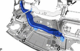
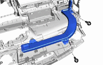
REMOVE NO. 1 HEATER TO REGISTER DUCT
-
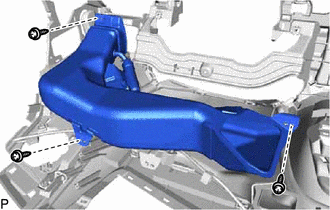
Remove the 3 screws <D> or <F>.
-
w/ Ion Generator:
-
Disengage the No. 1 heater to register duct from the ion generator sub-assembly.
-
-
Remove the No. 1 heater to register duct.
-
-
REMOVE NO. 4 HEATER TO REGISTER DUCT
-
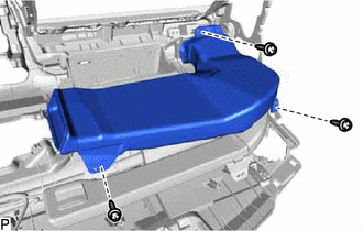
Remove the 3 screws <D> or <F> and No. 4 heater to register duct.
-
-
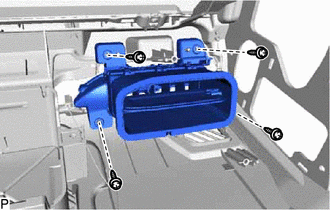
REMOVE DEFROSTER NOZZLE ASSEMBLY
-
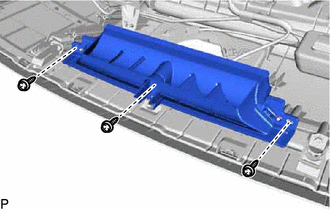
Remove the 3 screws <D> or <F> and defroster nozzle assembly.
-
-
REMOVE NO. 1 SIDE DEFROSTER NOZZLE DUCT
-
Remove the 3 screws <D> or <F> and No. 1 side defroster nozzle duct.
-
-
REMOVE NO. 2 SIDE DEFROSTER NOZZLE DUCT
-
Remove the 2 screws <D> or <F> and No. 2 side defroster nozzle duct
-
-
REMOVE ION GENERATOR SUB-ASSEMBLY (w/ Ion Generator)
-
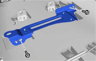
REMOVE NAVIGATION ANTENNA ASSEMBLY WITH BRACKET (w/ Navigation Antenna)
-
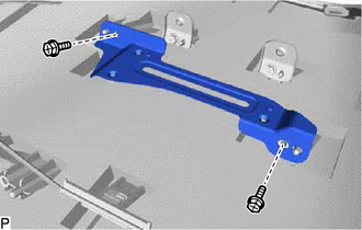
REMOVE NO. 2 INSTRUMENT PANEL REGISTER ASSEMBLY
-
Remove the 4 screws <D> and No. 2 instrument panel register assembly.
-
-
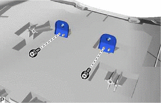
REMOVE NO. 1 ION GENERATOR BRACKET (w/ Ion Generator)
-
for LHD:
-
Remove the 2 screws <D> and No. 1 ion generator bracket.
-
-
for RHD:
-
Disengage the clamp.
-
Remove the 2 screws <D> and No. 1 ion generator bracket.
-
-
-
REMOVE NO. 1 METER HOOD RETAINER
-
Remove the 2 screws <D> and 2 No. 1 meter hood retainers.
-
-
REMOVE AUTOMATIC LIGHT CONTROL SENSOR
-
REMOVE NO. 1 DEFROSTER NOZZLE GARNISH
-
Disengage the 7 claws, 5 clips and 2 guides.
-
Disengage the 7 guides to remove the No. 1 defroster nozzle garnish.
-
-
REMOVE ANTENNA CORD SUB-ASSEMBLY
-
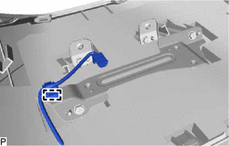
REMOVE NO. 2 INSTRUMENT PANEL WIRE
-
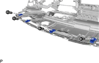
Disengage the 10 clamps to remove the No. 2 instrument panel wire.
-
-
REMOVE NO. 1 SIDE DEFROSTER NOZZLE
-
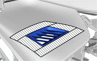

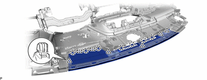
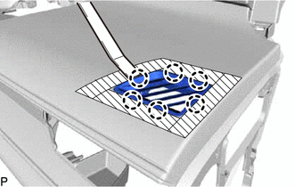
Protective Tape Apply protective tape to the areas shown in the illustration.
-
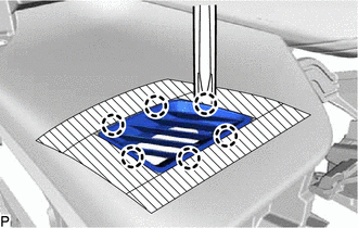
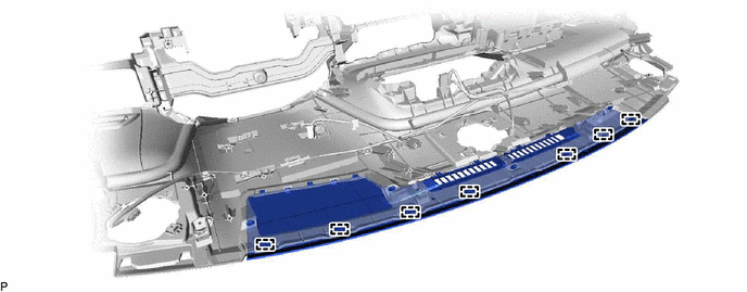
Using a moulding remover A, disengage the 6 claws to remove the No. 1 side defroster nozzle.
-
-
REMOVE NO. 2 SIDE DEFROSTER NOZZLE
-
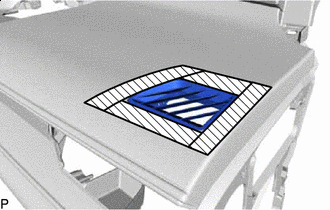
Protective Tape Apply protective tape to the areas shown in the illustration.
-
Using a moulding remover A, disengage the 6 claws to remove the No. 2 side defroster nozzle.
-
-
REMOVE NO. 1 INSTRUMENT PANEL PIN
-
Remove the 4 screws <D> or <E> and 4 No. 1 instrument panel pins.
-
-
REMOVE GLOVE COMPARTMENT DOOR LOCK CYLINDER ASSEMBLY
Note
Perform this procedure only when replacement of the glove compartment door assembly is necessary.
-
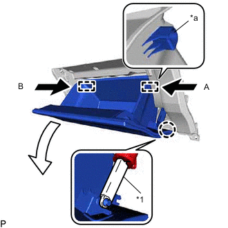
*1 Glove Compartment Door Stopper Sub-assembly *a Stopper Disengage the claw to disconnect the glove compartment door stopper sub-assembly.
-
Slightly bend stoppers (A) and (B) in the directions indicated by the arrows shown in the illustration and open the glove compartment door assembly until the stoppers are released.
-
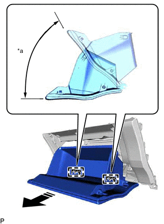
*a 52.5° 
Remove in this Direction Open the glove compartment door assembly to approximately 52.5° from its closed position. Pull it horizontally in the direction indicated by the arrow shown in the illustration to disengage the 2 hinges and remove the glove compartment door assembly.
Note
Pulling the glove compartment door assembly upward when removing it will cause the hinges to deform. Be sure to pull out the glove compartment door assembly horizontally.
-
Mark the glove compartment door assembly as shown in the illustration.
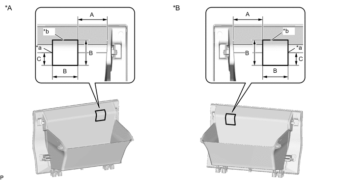
*A for LHD *B for RHD *a Edge of Curved Surface *b Marking Standard Measurement Area Measurement Area Measurement A 61.0 mm (2.402 in.) B 50.0 mm (1.969 in.) C 25.0 mm (0.984 in.) - - -
Insert a 3.0 mm (0.118 in.) drill bit into a drill.
-
Tape the 3.0 mm (0.118 in.) drill bit 10.0 mm (0.394 in.) from the tip as shown in the illustration.
Note
Tape the 3.0 mm (0.118 in.) drill bit to prevent the drill bit from going too deep.
-
Drill holes along the marking as shown in the illustration.
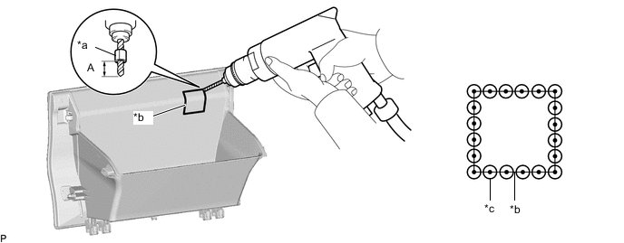
*a Tape *b Marking *c Drilled Hole - - Standard Measurement Area Measurement A 10.0 mm (0.394 in.) CAUTION:
-
In order to avoid injury, make sure to work carefully so that the tip of the drill does not slip.
-
Make sure to wear protective glasses when performing this procedure as shavings will fly about.
Note
To prevent the glove compartment door lock cylinder assembly from being damaged, make sure to only drill holes along the marking.
-
-
Insert a 7.0 mm (0.276 in.) drill bit into a drill.
-
Tape the 7.0 mm (0.276 in.) drill bit 10.0 mm (0.394 in.) from the tip as shown in the illustration.
Note
Tape the 7.0 mm (0.276 in.) drill bit to prevent the drill bit from going too deep.
-
Redrill each hole using the 7.0 mm (0.276 in.) drill bit.
CAUTION:
-
In order to avoid injury, make sure to center the tip of the drill in the pilot hole so that the tip of the drill does not slip.
-
Make sure to wear protective glasses when performing this procedure as shavings will fly about.
-
-
Using a plier nipper (side cutters), cut the glove compartment door assembly between each hole.
-
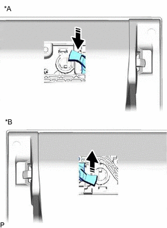
*A for LHD *B for RHD Move in this Direction Move the arm as shown in the illustration.
-
Press the cylinder lock to release it and pull out the glove compartment door lock cylinder assembly from the glove compartment door assembly to remove it as shown in the illustration.
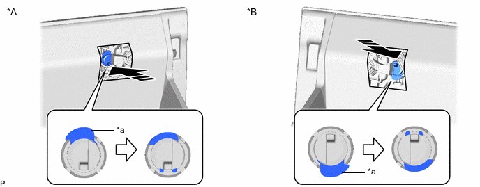
*A for LHD *B for RHD *a Cylinder Lock - - Remove in this Direction - -
-