AIR CONDITIONING SYSTEM Rear Blower Motor Circuit
DESCRIPTION
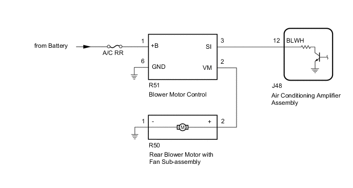
The rear blower motor with fan sub-assembly is operated by signals from the air conditioning amplifier assembly. Rear blower motor speed signals are transmitted in accordance with changes in the duty ratio.
WIRING DIAGRAM
CAUTION / NOTICE / HINT
Note
Inspect the fuses for circuits related to this system before performing the following procedure.
PROCEDURE
-
PERFORM ACTIVE TEST USING GTS
-
Connect the GTS to the DLC3.
-
Turn the engine switch on (IG).
-
Turn the GTS on.
-
Enter the following menus: Body Electrical / Air Conditioner / Active Test.
-
Check the operation by referring to the table below.
Body Electrical > Air Conditioner > Active TestTester Display Measurement Item Control Range Diagnostic Note Rear Blower Motor Rear blower motor with fan sub-assembly Min.: 0
Max.: 31
-
Body Electrical > Air Conditioner > Active TestTester Display Rear Blower Motor Result Proceed to OK NG
OK 
PROCEED TO NEXT SUSPECTED AREA SHOWN IN PROBLEM SYMPTOMS TABLE Click here
NG 
-
-
CHECK HARNESS AND CONNECTOR (BLOWER MOTOR CONTROL - POWER SOURCE AND BODY GROUND)
-
Disconnect the R51 blower motor control connector.
-
Measure the voltage and resistance according to the value(s) in the table below.
Standard Voltage Tester Connection Condition Specified Condition R51-1 (+B) - Body ground Always 11 to 14 V Standard Resistance Tester Connection Condition Specified Condition R51-6 (GND) - Body ground Always Below 1 Ω Result Proceed to OK NG
NG
REPAIR OR REPLACE HARNESS OR CONNECTOR
OK
-
-
CHECK HARNESS AND CONNECTOR (BLOWER MOTOR CONTROL - AIR CONDITIONING AMPLIFIER ASSEMBLY)
-
Disconnect the J48 air conditioning amplifier assembly connector.
-
Measure the resistance according to the value(s) in the table below.
Standard Resistance Tester Connection Condition Specified Condition J48-12 (BLWH) - R51-3 (SI) Always Below 1 Ω J48-12 (BLWH) or R51-3 (SI) - Other terminals and body ground Always 10 kΩ or higher Result Proceed to OK NG
NG
REPAIR OR REPLACE HARNESS OR CONNECTOR
OK
-
-
CHECK HARNESS AND CONNECTOR (REAR BLOWER MOTOR WITH FAN SUB-ASSEMBLY - BLOWER MOTOR CONTROL AND BODY GROUND)
-
Measure the resistance according to the value(s) in the table below.
Standard Resistance Tester Connection Condition Specified Condition R50-2 (+) - R51-2 (VM) Always Below 1 Ω R50-1 (-) - Body ground Always Below 1 Ω R50-2 (+) or R51-2 (VM) - Other terminals and body ground Always 10 kΩ or higher Result Proceed to OK NG
NG
REPAIR OR REPLACE HARNESS OR CONNECTOR
OK
-
-
INSPECT AIR CONDITIONING AMPLIFIER ASSEMBLY
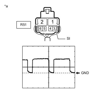
*a Component with harness connected
(Blower Motor Control)
-
Connect the J48 air conditioning amplifier assembly connector.
-
Measure the waveform.
OK Waveform is similar to that shown in the illustration. Item Content Terminal No. R51-3 (SI) - Body ground Tool Setting 2 V/DIV., 500 μs./DIV. Vehicle Condition
-
Engine switch on (IG)
-
Blower switch: LO
Tech Tips
The waveform varies with the blower level.
Result Proceed to OK NG -
NG
REPLACE AIR CONDITIONING AMPLIFIER ASSEMBLY Click here
OK
-
-
INSPECT REAR BLOWER MOTOR WITH FAN SUB-ASSEMBLY
-
Remove the rear blower motor with fan sub-assembly connector.
-
Inspect the rear blower motor with fan sub-assembly connector.
Result Proceed to OK NG
OK
REPLACE BLOWER MOTOR CONTROL Click here
NG
REPLACE REAR BLOWER MOTOR WITH FAN SUB-ASSEMBLY Click here
-