AIR CONDITIONING SYSTEM, Diagnostic DTC:B1447/47

| DTC Code | DTC Name |
|---|---|
| B1447/47 | Air Mix Damper Control Servo Motor Circuit (Rear) |
DESCRIPTION
The rear No. 2 cooling unit damper servo sub-assembly sends pulse signals to inform the air conditioning amplifier assembly of the damper position. The air conditioning amplifier assembly activates the motor (normal or reverse) based on these signals to move the rear No. 2 cooling unit damper servo sub-assembly to the appropriate position. As a result, the amount of air passing through the heater core after passing through the evaporator is adjusted, and the temperature of the air blowing toward the driver side is controlled.
The air conditioning amplifier communicates with the servo through a communication/driver IC and wiring assembly called the air conditioning harness assembly.
| DTC No. | Detection Item | DTC Detection Condition | Trouble Area | Memory |
|---|---|---|---|---|
| B1447/47 | Air Mix Damper Control Servo Motor Circuit (Rear) | Air outlet damper position does not change when the air conditioning amplifier assembly operates the rear No. 2 cooling unit damper servo sub-assembly. |
|
Memorized (30 seconds or more)* |
-
*: The air conditioning amplifier assembly stores this DTC if the malfunction has occurred for the period of time indicated in the brackets.
WIRING DIAGRAM
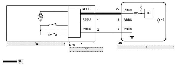
| *a | Rear No. 2 Cooling Unit Damper Servo Sub-assembly |
| *b | No. 2 Air Conditioning Harness Assembly |
| *c | Air Conditioning Amplifier Assembly |
| *d | LIN Communication Line |
CAUTION / NOTICE / HINT
Note
When the battery is disconnected, or the servo motor or air conditioning amplifier assembly is replaced, be sure to perform servo motor initialization.
Tech Tips
Confirm that there are no mechanical problems because this DTC may be stored when either a damper link or damper is mechanically locked.
PROCEDURE
-
READ VALUE USING GTS
-
Connect the GTS to the DLC3.
-
Turn the engine switch on (IG).
-
Turn the GTS on.
-
Operate the mode switch.
-
Enter the following menus: Body Electrical / Air Conditioner / Data List.
Body Electrical > Air Conditioner > Data ListTester Display Measurement Item Range Normal Condition Diagnostic Note Air Mix Servo Targ Pulse(R) Rear No. 2 cooling unit damper servo sub-assembly target pulse Min.: 128
Max.: 383
-
MAX COLD: 254 (pulse)
-
MAX HOT: 299 (pulse)
- Air Mix Servo Actual Pulse(R) Rear No. 2 cooling unit damper servo sub-assembly actual pulse Min.: 128
Max.: 383
-
MAX COLD: 254 (pulse)
-
MAX HOT: 299 (pulse)
-
Body Electrical > Air Conditioner > Data ListTester Display Air Mix Servo Targ Pulse(R) Air Mix Servo Actual Pulse(R) OK The display is as specified in the normal condition column. Result Result Proceed to Target pulse and actual pulse do not change A Target pulse changes but actual pulse does not change B Actual pulse changes following the target pulse (When troubleshooting according to the DTC) C Actual pulse changes following the target pulse (When troubleshooting according to Problem Symptoms Table) D -
A 
REPLACE AIR CONDITIONING AMPLIFIER ASSEMBLY Click here
C 
CHECK FOR DTC Click here
D
PROCEED TO NEXT SUSPECTED AREA SHOWN IN PROBLEM SYMPTOMS TABLE Click here
B 
-
-
CHECK REAR NO. 2 COOLING UNIT DAMPER SERVO SUB-ASSEMBLY
-
Replace the rear No. 2 cooling unit damper servo sub-assembly.
Tech Tips
Since the servo motor cannot be inspected while it is removed from the vehicle, replace the servo motor with a new or known good one and check that the condition returns to normal.
-
Connect the GTS to the DLC3.
-
Turn the engine switch on (IG).
-
Turn the GTS on.
-
Enter the following menus: Body Electrical / Air Conditioner / Trouble Codes.
-
Clear the DTC.
Body Electrical > Air Conditioner > Clear DTCs -
Check for DTCs.
Body Electrical > Air Conditioner > Trouble CodesOK DTC B1447/47 is not output. Result Proceed to OK NG
OK
END (REAR NO. 2 COOLING UNIT DAMPER SERVO SUB-ASSEMBLY IS DEFECTIVE)
NG
-
-
CHECK HARNESS AND CONNECTOR (NO. 2 AIR CONDITIONING HARNESS ASSEMBLY - AIR CONDITIONING AMPLIFIER ASSEMBLY)
-
Disconnect the R58 No. 2 air conditioning harness assembly connector.
-
Disconnect the J48 air conditioning amplifier assembly connector.
-
Measure the resistance according to the value(s) in the table below.
Standard Resistance Tester Connection Condition Specified Condition R58-2 (RBUG) - J48-2 (RBUG) Always Below 1 Ω R58-3 (RBUS) - J48-22 (RBUS) Always Below 1 Ω R58-4 (RBBU) - J48-3 (RBBU) Always Below 1 Ω R58-2 (RBUG) or J48-2 (RBUG) - Other terminals and body ground Always 10 kΩ or higher R58-3 (RBUS) or J48-22 (RBUS) - Other terminals and body ground Always 10 kΩ or higher R58-4 (RBBU) or J48-3 (RBBU) - Other terminals and body ground Always 10 kΩ or higher Result Proceed to OK NG
NG
REPAIR OR REPLACE HARNESS OR CONNECTOR
OK
-
-
CHECK AIR CONDITIONING HARNESS ASSEMBLY NO.2
-
Replace the No. 2 air conditioning harness assembly.
-
Connect the GTS to the DLC3.
-
Turn the engine switch on (IG).
-
Turn the GTS on.
-
Enter the following menus: Body Electrical / Air Conditioner / Trouble Codes.
-
Clear the DTC.
Body Electrical > Air Conditioner > Clear DTCs -
Check for DTCs.
Body Electrical > Air Conditioner > Trouble CodesOK DTC B1447/47 is not output. Result Proceed to OK NG
OK
END (NO. 2 AIR CONDITIONING HARNESS ASSEMBLY IS DEFECTIVE)
NG
REPLACE AIR CONDITIONING AMPLIFIER ASSEMBLY Click here
-
-
CHECK FOR DTC
-
Connect the GTS to the DLC3.
-
Turn the engine switch on (IG).
-
Turn the GTS on.
-
Enter the following menus: Body Electrical / Air Conditioner / Trouble Codes.
-
Clear the DTC.
Body Electrical > Air Conditioner > Clear DTCs -
Check for DTCs.
Body Electrical > Air Conditioner > Trouble CodesOK DTC B1447/47 is not output. Result Proceed to OK NG
OK
USE SIMULATION METHOD TO CHECK Click here
NG
REPLACE AIR CONDITIONING AMPLIFIER ASSEMBLY Click here
-