AIR CONDITIONING SYSTEM, Diagnostic DTC:B1443/43

| DTC Code | DTC Name |
|---|---|
| B1443/43 | Air Outlet Damper Control Servo Motor Circuit |
DESCRIPTION
- for LHD:
The No. 2 air conditioning radiator damper servo sub-assembly sends pulse signals to inform the air conditioning amplifier assembly of the damper position. The air conditioning amplifier assembly activates the motor (normal or reverse) based on these signals to move the No. 2 air conditioning radiator damper servo sub-assembly to the appropriate position, which controls the air outlet switching.
The air conditioning amplifier assembly communicates with the servo through a communication/driver IC and wiring assembly called the air conditioning harness assembly.
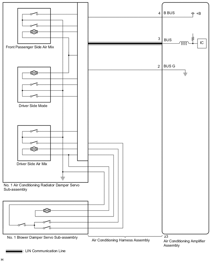
- for RHD:
The No. 1 air conditioning radiator damper servo sub-assembly (driver side mode) sends pulse signals to inform the air conditioning amplifier assembly of the damper position. The air conditioning amplifier assembly activates the motor (normal or reverse) based on these signals to move the No. 1 air conditioning radiator damper servo sub-assembly (driver side mode) to the appropriate position, which controls the air outlet switching.
The air conditioning amplifier assembly communicates with the servo through a communication/driver IC and wiring assembly called the air conditioning harness assembly.
| DTC No. | Detection Item | DTC Detection Condition | Trouble Area | Memory |
|---|---|---|---|---|
| B1443/43 | Air Outlet Damper Control Servo Motor Circuit |
for LHD:
for RHD: |
|
Memorized (30 sec. or more)*1 |
-
*1: The air conditioning amplifier assembly stores this DTC if the malfunction has occurred for the period of time indicated in the brackets.
-
*2: for LHD
-
*3: for RHD
WIRING DIAGRAM
Figure 1. for LHD:
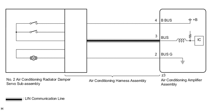
Figure 2. for RHD:
CAUTION / NOTICE / HINT
Tech Tips
Confirm that no mechanical problem is present because this DTC can be output when either a damper link or damper is mechanically locked.
PROCEDURE
-
CONFIRM MODEL
-
Choose the model to be inspected.
Result Result Proceed to for LHD A for RHD B
B 
READ VALUE USING GTS Click here
A 
-
-
READ VALUE USING GTS
-
Connect the GTS to the DLC3.
-
Turn the engine switch on (IG).
-
Turn the GTS on.
-
Operate the mode switch.
-
Enter the following menus: Body Electrical / Air Conditioner / Data List.
-
Read the Data List according to the display on the GTS.
Body Electrical > Air Conditioner > Data ListTester Display Measurement Item Range Normal Condition Diagnostic Note Air Outlet Servo Pulse (D) No. 2 air conditioning radiator damper servo sub-assembly target pulse Min.: 128
Max.: 383
-
FACE: 256 (pulse)
-
FACE1: 256 (pulse)
-
FACE2: 256 (pulse)
-
B/L: 245 (pulse)
-
B/L2: 245 (pulse)
-
FOOT-R: 215 (pulse)
-
FOOT-M: 215 (pulse)
-
FOOT: 215 (pulse)
-
FOOT-D: 207 (pulse)
-
FOOT-0: 224 (pulse)
-
FOOT-F: 215 (pulse)
-
FOOT/DEF: 192 (pulse)
-
DEF: 164 (pulse)
-
S-FLOW (Single Seat Control Modes): 164 (pulse)
- Air Outlet Servo Actu Pulse(D) No. 2 air conditioning radiator damper servo sub-assembly actual pulse Min.: 128
Max.: 383
-
FACE: 256 (pulse)
-
FACE1: 256 (pulse)
-
FACE2: 256 (pulse)
-
B/L: 245 (pulse)
-
B/L2: 245 (pulse)
-
FOOT-R: 215 (pulse)
-
FOOT-M: 215 (pulse)
-
FOOT: 215 (pulse)
-
FOOT-D: 207 (pulse)
-
FOOT-0: 224 (pulse)
-
FOOT-F: 215 (pulse)
-
FOOT/DEF: 192 (pulse)
-
DEF: 164 (pulse)
-
S-FLOW (Single Seat Control Modes): 164 (pulse)
-
Body Electrical > Air Conditioner > Data ListTester Display Air Outlet Servo Pulse (D) Air Outlet Servo Actu Pulse(D) OK When the mode switch is operated, the actual pulse changes following the target pulse. Result Result Proceed to Target pulse changes but actual pulse does not change A Target pulse and actual pulse do not change B Actual pulse changes following the target pulse (When troubleshooting according to the DTC) C Actual pulse changes following the target pulse (When troubleshooting according to Problem Symptoms Table) D -
B 
REPLACE AIR CONDITIONING AMPLIFIER ASSEMBLY Click here
C
RECONFIRM DTC OUTPUT Click here
D
PROCEED TO NEXT SUSPECTED AREA SHOWN IN PROBLEM SYMPTOMS TABLE Click here
A
-
-
REPLACE NO. 2 AIR CONDITIONING RADIATOR DAMPER SERVO SUB-ASSEMBLY
-
Replace the No. 2 air conditioning radiator damper servo sub-assembly.
Tech Tips
Since the servo motor cannot be inspected while it is removed from the vehicle, replace the servo motor with a new or known good one and check that the condition returns to normal.
-
Check for DTCs.
Body Electrical > Air Conditioner > Trouble CodesResult Result Proceed to DTC B1443/43 is output A DTC B1443/43 is not output B
B
END (NO. 2 AIR CONDITIONING RADIATOR DAMPER SERVO SUB-ASSEMBLY WAS DEFECTIVE)
A
-
-
REPLACE AIR CONDITIONING HARNESS ASSEMBLY
-
Replace the air conditioning harness assembly.
Tech Tips
Since the air conditioning harness assembly cannot be inspected while it is removed from the vehicle, replace the air conditioning harness assembly with a new or known good one and check that the condition returns to normal.
-
Check for DTCs.
Body Electrical > Air Conditioner > Trouble CodesResult Result Proceed to DTC B1443/43 is output A DTC B1443/43 is not output B
A
REPLACE AIR CONDITIONING AMPLIFIER ASSEMBLY Click here
B
END (AIR CONDITIONING HARNESS ASSEMBLY WAS DEFECTIVE)
-
-
RECONFIRM DTC OUTPUT
-
Check for DTCs.
Body Electrical > Air Conditioner > Trouble CodesResult Result Proceed to DTC B1443/43 is output A DTC B1443/43 is not output B
A
REPLACE AIR CONDITIONING AMPLIFIER ASSEMBLY Click here
B
USE SIMULATION METHOD TO CHECK Click here
-
-
READ VALUE USING GTS
-
Connect the GTS to the DLC3.
-
Turn the engine switch on (IG).
-
Turn the GTS on.
-
Operate the mode switch.
-
Enter the following menus: Body Electrical / Air Conditioner / Data List.
-
Read the Data List according to the display on the GTS.
Body Electrical > Air Conditioner > Data ListTester Display Measurement Item Range Normal Condition Diagnostic Note Air Outlet Servo Pulse (D) No. 1 air conditioning radiator damper servo sub-assembly (driver side mode) target pulse Min.: 128
Max.: 383
-
FACE: 256 (pulse)
-
FACE1: 256 (pulse)
-
FACE2: 256 (pulse)
-
B/L: 267 (pulse)
-
B/L2: 267 (pulse)
-
FOOT-R: 297 (pulse)
-
FOOT-M: 297 (pulse)
-
FOOT: 297 (pulse)
-
FOOT-D: 305 (pulse)
-
FOOT-0: 288 (pulse)
-
FOOT-F: 297 (pulse)
-
FOOT/DEF: 320 (pulse)
-
DEF: 348 (pulse)
-
S-FLOW (Single Seat Control Modes): 348 (pulse)
- Air Outlet Servo Actu Pulse(D) No. 1 air conditioning radiator damper servo sub-assembly (driver side mode) actual pulse Min.: 128
Max.: 383
-
FACE: 256 (pulse)
-
FACE1: 256 (pulse)
-
FACE2: 256 (pulse)
-
B/L: 267 (pulse)
-
B/L2: 267 (pulse)
-
FOOT-R: 297 (pulse)
-
FOOT-M: 297 (pulse)
-
FOOT: 297 (pulse)
-
FOOT-D: 305 (pulse)
-
FOOT-0: 288 (pulse)
-
FOOT-F: 297 (pulse)
-
FOOT/DEF: 320 (pulse)
-
DEF: 348 (pulse)
-
S-FLOW (Single Seat Control Modes): 348 (pulse)
-
Body Electrical > Air Conditioner > Data ListTester Display Air Outlet Servo Pulse (D) Air Outlet Servo Actu Pulse(D) OK When the mode switch is operated, the actual pulse changes following the target pulse. Result Result Proceed to Target pulse changes but actual pulse does not change A Target pulse and actual pulse do not change B Actual pulse changes following the target pulse (When troubleshooting according to the DTC) C Actual pulse changes following the target pulse (When troubleshooting according to Problem Symptoms Table) D -
B
REPLACE AIR CONDITIONING AMPLIFIER ASSEMBLY Click here
C
RECONFIRM DTC OUTPUT Click here
D
PROCEED TO NEXT SUSPECTED AREA SHOWN IN PROBLEM SYMPTOMS TABLE Click here
A
-
-
REPLACE NO. 1 AIR CONDITIONING RADIATOR DAMPER SERVO SUB-ASSEMBLY
-
Replace the No. 1 air conditioning radiator damper servo sub-assembly.
Tech Tips
Since the servo motor cannot be inspected while it is removed from the vehicle, replace the servo motor with a new or known good one and check that the condition returns to normal.
-
Check for DTCs.
Body Electrical > Air Conditioner > Trouble CodesResult Result Proceed to DTC B1443/43 is output A DTC B1443/43 is not output B
B
END (NO. 1 AIR CONDITIONING RADIATOR DAMPER SERVO SUB-ASSEMBLY WAS DEFECTIVE)
A
-
-
REPLACE AIR CONDITIONING HARNESS ASSEMBLY
-
Replace the air conditioning harness assembly.
Tech Tips
Since the air conditioning harness assembly cannot be inspected while it is removed from the vehicle, replace the air conditioning harness assembly with a new or known good one and check that the condition returns to normal.
-
Check for DTCs.
Body Electrical > Air Conditioner > Trouble CodesResult Result Proceed to DTC B1443/43 is output A DTC B1443/43 is not output B
A
REPLACE AIR CONDITIONING AMPLIFIER ASSEMBLY Click here
B
END (AIR CONDITIONING HARNESS ASSEMBLY WAS DEFECTIVE)
-
-
RECONFIRM DTC OUTPUT
-
Check for DTCs.
Body Electrical > Air Conditioner > Trouble CodesResult Result Proceed to DTC B1443/43 is output A DTC B1443/43 is not output B
A
REPLACE AIR CONDITIONING AMPLIFIER ASSEMBLY Click here
B
USE SIMULATION METHOD TO CHECK Click here
-