BACK DOOR CLOSER SYSTEM Back Door cannot be Opened
DESCRIPTION
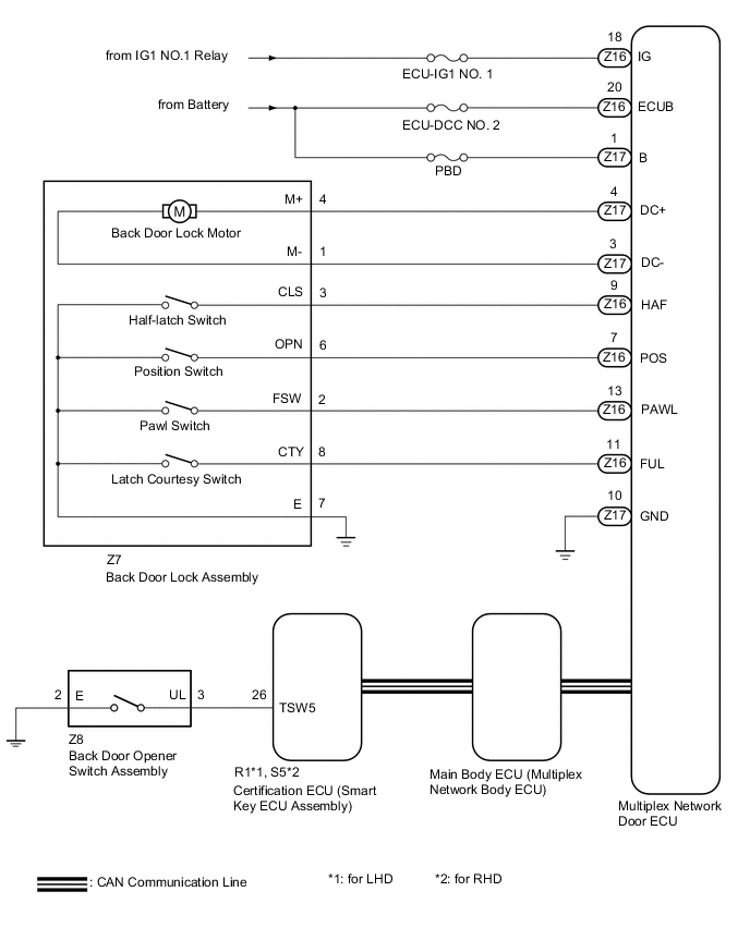
When the back door cannot be opened, one of the following may be malfunctioning: 1) the multiplex network door ECU, 2) back door lock assembly, 3) back door opener switch assembly, 4) main body ECU (multiplex network body ECU) or 5) certification ECU (smart key ECU assembly).
WIRING DIAGRAM
CAUTION / NOTICE / HINT
Note
-
Inspect the fuses for circuits related to this system before performing the following procedure.
-
If the certification ECU (smart key ECU assembly) or main body ECU (multiplex network body ECU) is replaced, refer to Service Bulletin.
-
If the certification ECU (smart key ECU assembly) is replaced, refer to Service Bulletin.
-
If the main body ECU (multiplex network body ECU) is replaced, refer to Service Bulletin.
-
The back door closer system uses the CAN communication system. First, confirm that there are no malfunctions in the CAN communication system. Refer to How to Proceed with Troubleshooting.
-
As the door control battery is installed between the vehicle battery and main body ECU (multiplex network body ECU), first perform the inspections in On-Vehicle Inspection to confirm that there are no malfunctions in the power source circuit for the main body ECU (multiplex network body ECU) before performing this troubleshooting procedure.*
-
*: w/o Canister Pump Module with Door Ajar Warning Function
PROCEDURE
-
CHECK FOR DTC
-
Check for DTCs.
Body Electrical > Back Door > Trouble CodesResult Result Proceed to DTCs are not output A DTC B2250 is output B DTC B2251 is output C
B 
GO TO DTC CHART Click here
C
GO TO DTC CHART Click here
A 
-
-
CHECK BASIC FUNCTIONS
-
Check the basic functions of the power door lock.
OK The basic functions of the power door lock can be operated normally. Result Proceed to OK NG
NG
GO TO POWER DOOR LOCK CONTROL SYSTEM Click here
OK
-
-
READ VALUE USING GTS (Back Door Open)
-
Connect the GTS to the DLC3.
-
Turn the engine switch on (IG).
-
Turn the GTS on.
-
Enter the following menus: Body Electrical / Main Body / Data List.
-
Read the Data List according to the display on the GTS.
Body Electrical > Main Body > Data ListTester Display Measurement Item Range Normal Condition Diagnostic Note Back Door Open Back door condition signal Prohibit or Permit Prohibit: Back door locked
Permit: Back door unlocked
-
Body Electrical > Main Body > Data ListTester Display Back Door Open OK On the GTS screen, Permit or Prohibit is displayed accordingly. Result Proceed to OK NG
NG
REPLACE MAIN BODY ECU (MULTIPLEX NETWORK BODY ECU) Click here
OK
-
-
READ VALUE USING GTS (Door Lock Status)
-
Connect the GTS to the DLC3.
-
Turn the engine switch on (IG).
-
Turn the GTS on.
-
Enter the following menus: Body Electrical / Back Door / Data List.
-
Read the Data List according to the display on the GTS.
Body Electrical > Back Door > Data ListTester Display Measurement Item Range Normal Condition Diagnostic Note Door Lock Status Back door lock condition signal Lock or Unlock Lock: Back door locked
Unlock: Back door unlocked
-
Body Electrical > Back Door > Data ListTester Display Door Lock Status OK On the GTS screen, Lock or Unlock is displayed accordingly. Result Proceed to OK NG
NG
REPLACE MULTIPLEX NETWORK DOOR ECU Click here
OK
-
-
READ VALUE USING GTS (Tr/B-Door Unlock SW)
-
Connect the GTS to the DLC3.
-
Turn the engine switch on (IG).
-
Turn the GTS on.
-
Enter the following menus: Body Electrical / Entry&Start / Data List.
-
Read the Data List according to the display on the GTS.
Body Electrical > Entry&Start > Data ListTester Display Measurement Item Range Normal Condition Diagnostic Note Tr/B-Door Unlock SW Back door opener switch assembly signal OFF or ON OFF: Back door opener switch assembly off
ON: Back door opener switch assembly on
-
Body Electrical > Entry&Start > Data ListTester Display Tr/B-Door Unlock SW OK On the GTS screen, ON or OFF is displayed accordingly. Result Proceed to OK NG
NG 
INSPECT BACK DOOR OPENER SWITCH ASSEMBLY Click here
OK
-
-
INSPECT BACK DOOR LOCK ASSEMBLY
-
Remove the back door lock assembly.
-
Inspect the back door lock assembly.
Result Proceed to OK NG
NG
REPLACE BACK DOOR LOCK ASSEMBLY Click here
OK
-
-
CHECK HARNESS AND CONNECTOR (BACK DOOR LOCK ASSEMBLY - MULTIPLEX NETWORK DOOR ECU AND BODY GROUND)
-
Disconnect the Z7 back door lock assembly connector.
-
Disconnect the Z16 and Z17 multiplex network door ECU connectors.
-
Measure the resistance according to the value(s) in the table below.
Standard Resistance Tester Connection Condition Specified Condition Z7-4 (M+) - Z17-4 (DC+) Always Below 1 Ω Z7-1 (M-) - Z17-3 (DC-) Always Below 1 Ω Z7-8 (CTY) - Z16-11 (FUL) Always Below 1 Ω Z7-2 (FSW) - Z16-13 (PAWL) Always Below 1 Ω Z7-3 (CLS) - Z16-9 (HAF) Always Below 1 Ω Z7-6 (OPN) - Z16-7 (POS) Always Below 1 Ω Z7-7 (E) - Body ground Always Below 1 Ω Z7-4 (M+) or Z17-4 (DC+) - Body ground Always 10 kΩ or higher Z7-1 (M-) or Z17-3 (DC-) - Body ground Always 10 kΩ or higher Z7-2 (FSW) or Z16-13 (PAWL) - Body ground Always 10 kΩ or higher Z7-8 (CTY) or Z16-11 (FUL) - Body ground Always 10 kΩ or higher Z7-3 (CLS) or Z16-9 (HAF) - Body ground Always 10 kΩ or higher Z7-6 (OPN) or Z16-7 (POS) - Body ground Always 10 kΩ or higher Result Proceed to OK NG
NG
REPAIR OR REPLACE HARNESS OR CONNECTOR
OK
-
-
REPLACE MULTIPLEX NETWORK DOOR ECU
-
Temporarily replace the multiplex network door ECU with a new or known good one.
Result Proceed to NEXT
NEXT
-
-
CHECK BACK DOOR OPEN OPERATION
-
Check the back door open operation.
Result Result Proceed to Back door can be opened A Back door cannot be opened B
A
END (MULTIPLEX NETWORK DOOR ECU WAS DEFECTIVE)
B
REPLACE MAIN BODY ECU (MULTIPLEX NETWORK BODY ECU) Click here
-
-
INSPECT BACK DOOR OPENER SWITCH ASSEMBLY
-
Remove the back door opener switch assembly.
-
Inspect the back door opener switch assembly.
Result Proceed to OK NG
NG
REPLACE BACK DOOR OPENER SWITCH ASSEMBLY Click here
OK
-
-
CHECK HARNESS AND CONNECTOR (BACK DOOR OPENER SWITCH ASSEMBLY - CERTIFICATION ECU (SMART KEY ECU ASSEMBLY) AND BODY GROUND)
-
Disconnect the Z8 back door opener switch assembly connector.
-
Disconnect the R1*1 or S5*2 certification ECU (smart key ECU assembly) connector.
-
*1: for LHD
-
*2: for RHD
-
-
Measure the resistance according to the value(s) in the table below.
Standard Resistance for LHD Tester Connection Condition Specified Condition Z8-3 (UL) - R1-26 (TSW5) Always Below 1 Ω Z8-2 (E) - Body ground Always Below 1 Ω Z8-3 (UL) or R1-26 (TSW5) - Body ground Always 10 kΩ or higher for RHD Tester Connection Condition Specified Condition Z8-3 (UL) - S5-26 (TSW5) Always Below 1 Ω Z8-2 (E) - Body ground Always Below 1 Ω Z8-3 (UL) or S5-26 (TSW5) - Body ground Always 10 kΩ or higher Result Proceed to OK NG
OK
REPLACE CERTIFICATION ECU (SMART KEY ECU ASSEMBLY)
NG
REPAIR OR REPLACE HARNESS OR CONNECTOR
-