POWER BACK DOOR SYSTEM Jam Protection Function Activates During Power Back Door Operation
DESCRIPTION
If the jam protection function activates during power back door operation, one of the following may be the cause: 1) improper fit of back door or a foreign object stuck in the back door, 2) malfunction in the power back door sensor assembly circuit or 3) multiplex network door ECU malfunction.
WIRING DIAGRAM
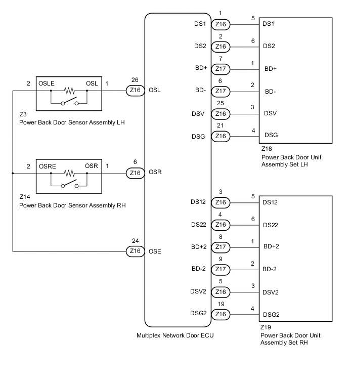
CAUTION / NOTICE / HINT
Note
If the multiplex network door ECU has been removed and installed or replaced, or if any of the connectors has been disconnected, initialize the power back door system.
PROCEDURE
-
CHECK POWER BACK DOOR SYSTEM
-
Check if there are any foreign objects interfering with back door operation.
Result Result Proceed to There are no foreign objects A There are foreign objects B
B 
REMOVE FOREIGN OBJECT
A 
-
-
CHECK BACK DOOR OPERATION
-
Check back door operation.
-
Set the customize setting "Power Back Door Function" on the multi-information display to OFF.
Note
This check is possible only when the "Power Back Door Function" customize setting is set to OFF on the multi-information display in the combination meter assembly. (The default setting is ON.)
-
Open/close the back door by hand.
Result Result Proceed to The back door fully opens and closes smoothly A The back door does not fully open and close smoothly B -
-
Set the customize setting "Power Back Door Function" on the multi-information display to ON.
Note
The "Power Back Door Function" customize setting is set to ON on the multi-information display in the combination meter assembly must be set to ON for the power back door system to operate.
B
ADJUST BACK DOOR
A
-
-
READ VALUE USING GTS
-
Connect the GTS to the DLC3.
-
Turn the engine switch on (IG).
-
Turn the GTS on.
-
Enter the following menus: Body Electrical / Back Door / Data List.
-
Read the Data List according to the display on the GTS.
Body Electrical > Back Door > Data ListTester Display Measurement Item Range Normal Condition Diagnostic Note PBD Touch Sensor (Right) Power back door sensor assembly RH signal OFF, ON or Open OFF: Power back door sensor assembly RH not pressed
ON: Power back door sensor assembly RH pressed
Open: Power back door sensor assembly RH circuit open
- PBD Touch Sensor (Left) Power back door sensor assembly LH signal OFF, ON or Open OFF: Power back door sensor assembly LH not pressed
ON: Power back door sensor assembly LH pressed
Open: Power back door sensor assembly LH circuit open
-
Body Electrical > Back Door > Data ListTester Display PBD Touch Sensor (Right) PBD Touch Sensor (Left) Result Result Proceed to On the GTS screen, ON or OFF is displayed accordingly A On the GTS screen, ON or OFF is not displayed accordingly or Open is displayed for power back door sensor assembly RH B On the GTS screen, ON or OFF is not displayed accordingly or Open is displayed for power back door sensor assembly LH C
B 
INSPECT POWER BACK DOOR SENSOR ASSEMBLY RH Click here
C
INSPECT POWER BACK DOOR SENSOR ASSEMBLY LH Click here
A
-
-
REPLACE POWER BACK DOOR UNIT ASSEMBLY SET
-
Replace the power back door unit assembly set with a new or known good one.
Result Proceed to NEXT
NEXT
-
-
CHECK POWER BACK DOOR SYSTEM
-
Check the power back door system operation.
OK Power back door system operates normally Result Proceed to OK NG
OK
END (POWER BACK DOOR UNIT ASSEMBLY SET WAS MALFUNCTIONING)
NG
REPLACE MULTIPLEX NETWORK DOOR ECU Click here
-
-
INSPECT POWER BACK DOOR SENSOR ASSEMBLY RH
-
Remove the power back door sensor assembly RH.
-
Inspect the power back door sensor assembly RH.
Result Proceed to OK NG
NG
REPLACE POWER BACK DOOR SENSOR ASSEMBLY RH Click here
OK
-
-
CHECK HARNESS AND CONNECTOR (POWER BACK DOOR SENSOR ASSEMBLY RH - MULTIPLEX NETWORK DOOR ECU)
-
Disconnect the Z14 power back door sensor assembly RH connector.
-
Disconnect the Z16 multiplex network door ECU connector.
-
Measure the resistance according to the value(s) in the table below.
Standard Resistance Tester Connection Condition Specified Condition Z14-1 (OSR) - Z16-6 (OSR) Always Below 1 Ω Z14-2 (OSRE) - Z16-24 (OSE) Always Below 1 Ω Z14-1 (OSR) or Z16-6 (OSR) - Body ground Always 10 kΩ or higher Z14-2 (OSRE) or Z16-24 (OSE) - Body ground Always 10 kΩ or higher Result Proceed to OK NG
OK
REPLACE MULTIPLEX NETWORK DOOR ECU Click here
NG
REPAIR OR REPLACE HARNESS OR CONNECTOR
-
-
INSPECT POWER BACK DOOR SENSOR ASSEMBLY LH
-
Remove the power back door sensor assembly LH.
-
Inspect the power back door sensor assembly LH.
Result Proceed to OK NG
NG
REPLACE POWER BACK DOOR SENSOR ASSEMBLY LH Click here
OK
-
-
CHECK HARNESS AND CONNECTOR (POWER BACK DOOR SENSOR ASSEMBLY LH - MULTIPLEX NETWORK DOOR ECU)
-
Disconnect the Z3 power back door sensor assembly LH connector.
-
Disconnect the Z16 multiplex network door ECU connector.
-
Measure the resistance according to the value(s) in the table below.
Standard Resistance Tester Connection Condition Specified Condition Z3-1 (OSL) - Z16-26 (OSL) Always Below 1 Ω Z3-2 (OSLE) - Z16-24 (OSE) Always Below 1 Ω Z3-1 (OSL) or Z16-26 (OSL) - Body ground Always 10 kΩ or higher Z3-2 (OSLE) or Z16-24 (OSE) - Body ground Always 10 kΩ or higher Result Proceed to OK NG
OK
REPLACE MULTIPLEX NETWORK DOOR ECU Click here
NG
REPAIR OR REPLACE HARNESS OR CONNECTOR
-