POWER BACK DOOR SYSTEM Power Back Door cannot be Opened Using the Back Door Opener Switch
DESCRIPTION
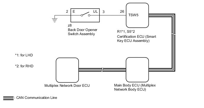
The multiplex network door ECU receives open request signals from the back door opener switch assembly via CAN communication.
WIRING DIAGRAM
CAUTION / NOTICE / HINT
Note
-
The power back door system uses the CAN communication system. Inspect the communication function by following How to Proceed with Troubleshooting. Troubleshoot the power back door system after confirming that the CAN communication system is functioning properly.
-
If the multiplex network door ECU has been removed and installed or replaced, or if any of the connectors has been disconnected, initialize the power back door system.
-
If the main body ECU (multiplex network body ECU) or certification ECU (smart key ECU assembly) is replaced, refer to Service Bulletin.
-
The following troubleshooting procedure is based on the premise that the entry and start system (for Entry Function) is operating normally. Check the entry and start system (for Entry Function) before troubleshooting the power back door system.
-
As the door control battery is installed between the vehicle battery and main body ECU (multiplex network body ECU), inspect the main body ECU (multiplex network body ECU) power source circuit for malfunctions before performing this troubleshooting procedure.*
-
*: w/o Canister Pump Module with Door Ajar Warning Function
PROCEDURE
-
READ VALUE USING GTS
-
Connect the GTS to the DLC3.
-
Turn the engine switch on (IG).
-
Turn the GTS on.
-
Enter the following menus: Body Electrical / Entry&Start / Data List.
-
Read the Data List according to the display on the GTS.
Body Electrical > Entry&Start > Data ListTester Display Measurement Item Range Normal Condition Diagnostic Note Tr/B-Door Unlock SW Back door opener switch assembly (open switch) signal OFF or ON OFF: Back door opener switch assembly (open switch) off
ON: Back door opener switch assembly (open switch) on
-
Body Electrical > Entry&Start > Data ListTester Display Tr/B-Door Unlock SW OK On the GTS screen, ON or OFF is displayed accordingly. Result Proceed to OK NG
NG 
INSPECT BACK DOOR OPENER SWITCH ASSEMBLY Click here
OK 
-
-
REPLACE MULTIPLEX NETWORK DOOR ECU
-
Replace the multiplex network door ECU with a new or known good one.
Result Proceed to NEXT
NEXT
-
-
INITIALIZE MULTIPLEX NETWORK DOOR ECU
-
Initialize the multiplex network door ECU.
Result Proceed to NEXT
NEXT
-
-
CHECK POWER BACK DOOR SYSTEM
-
Check the power back door system operation.
OK Power back door system operates normally Result Proceed to OK NG
OK 
END (MULTIPLEX NETWORK DOOR ECU WAS MALFUNCTIONING)
NG
REPLACE MAIN BODY ECU (MULTIPLEX NETWORK BODY ECU) Click here
-
-
INSPECT BACK DOOR OPENER SWITCH ASSEMBLY
-
Remove the back door opener switch assembly.
-
Inspect the back door opener switch assembly
Result Proceed to OK NG
NG
REPLACE BACK DOOR OPENER SWITCH ASSEMBLY Click here
OK
-
-
CHECK HARNESS AND CONNECTOR (BACK DOOR OPENER SWITCH ASSEMBLY - CERTIFICATION ECU [SMART KEY ECU ASSEMBLY])
-
Disconnect the z8 back door opener switch assembly connector.
-
Disconnect the R1*1 or S5*2 certification ECU (smart key ECU assembly) connector.
-
*1: for LHD
-
*2: for RHD
-
-
Measure the resistance according to the value(s) in the table below.
Standard Resistance for LHD Tester Connection Condition Specified Condition z8-3 (UL) - R1-26 (TSW5) Always Below 1 Ω z8-2 (E) - Body ground Always Below 1 Ω z8-3 (UL) or R1-26 (TSW5) - Body ground Always 10 kΩ or higher for RHD Tester Connection Condition Specified Condition z8-3 (UL) - S5-26 (TSW5) Always Below 1 Ω z8-2 (E) - Body ground Always Below 1 Ω z8-3 (UL) or S5-26 (TSW5) - Body ground Always 10 kΩ or higher Result Proceed to OK NG
OK
REPLACE CERTIFICATION ECU (SMART KEY ECU ASSEMBLY)
NG
REPAIR OR REPLACE HARNESS OR CONNECTOR
-