POWER BACK DOOR SYSTEM Power Back Door cannot be Operated Using Any Switch
DESCRIPTION
If the power back door system cannot be operated using any switch, one of the following may be the cause: 1) the multiplex network door ECU has not been initialized, 2) malfunction in the power back door sensor assembly circuit, 3) CAN communication system, 4) back door closer system malfunction, 5) meter/gauge system malfunction, 6) malfunction in the multiplex network door ECU power source circuit or 7) multiplex network door ECU malfunction.
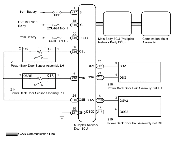
WIRING DIAGRAM
CAUTION / NOTICE / HINT
Note
-
The power back door system uses the CAN communication system. Inspect the communication function by following How to Proceed with Troubleshooting. Troubleshoot the power back door system after confirming that the CAN communication system is functioning properly.
-
Inspect the fuses for circuits related to this system before performing the following procedure.
-
This check is possible only when the "Power Back Door Function" customize setting is set to ON on the multi-information display in the combination meter assembly. (The default setting is ON.)
-
If the multiplex network door ECU has been removed and installed or replaced, or if any of the connectors has been disconnected, initialize the power back door system.
PROCEDURE
-
INITIALIZE MULTIPLEX NETWORK DOOR ECU
-
Initialize the multiplex network door ECU.
Result Proceed to NEXT
NEXT 
-
-
CHECK POWER BACK DOOR SYSTEM
-
Check the power back door system operation.
OK Power back door system operates normally Result Proceed to OK NG
OK 
END (POWER BACK DOOR SYSTEM HAS NOT BEEN INITIALIZED)
NG
-
-
CHECK BACK DOOR CLOSER SYSTEM
-
Check the back door closer system operation.
OK Back door closer system operates normally Result Proceed to OK NG
NG
GO TO BACK DOOR CLOSER SYSTEM Click here
OK
-
-
CHECK COMBINATION METER ASSEMBLY
-
Check the shift position indicator operation and check that the speedometer indicates 0 km/h (0 mph) when the vehicle is stopped with the engine idling.
OK Combination meter operates normally Result Proceed to OK NG
NG
GO TO METER / GAUGE SYSTEM Click here
OK
-
-
CHECK FOR DTC
-
Check for DTCs.
Body Electrical > Back Door > Trouble CodesOK DTCs are not output Result Proceed to OK NG
NG
GO TO DIAGNOSTIC TROUBLE CODE CHART Click here
OK
-
-
CHECK HARNESS AND CONNECTOR (MULTIPLEX NETWORK DOOR ECU - BATTERY AND BODY GROUND)
-
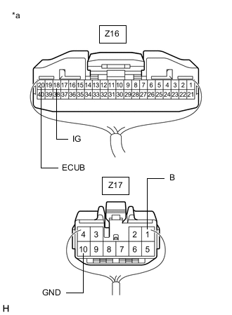
*a Rear view of wire harness connector
(to Multiplex Network Door ECU)
Disconnect the Z16 and Z17 multiplex network door ECU connectors.
-
Measure the resistance according to the value(s) in the table below.
Standard Resistance Tester Connection Condition Specified Condition Z17-10 (GND) - Body ground Always Below 1 Ω -
Measure the voltage according to the value(s) in the table below.
Standard Voltage Tester Connection Condition Specified Condition Z16-20 (ECUB) - Body ground Always 11 to 14 V Z17-1 (B) - Body ground Always 11 to 14 V Z16-18 (IG) - Body ground Engine switch on (IG) 11 to 14 V Engine switch off Below 1 V Result Proceed to OK NG
NG
REPAIR OR REPLACE HARNESS OR CONNECTOR
OK
-
-
READ VALUE USING GTS (PBD Main SW)
-
Connect the GTS to the DLC3.
-
Turn the engine switch on (IG).
-
Turn the GTS on.
-
Enter the following menus: Body Electrical / Back Door / Data List.
-
Read the Data List according to the display on the GTS.
Body Electrical > Back Door > Data ListTester Display Measurement Item Range Normal Condition Diagnostic Note PBD Main SW Power back door ON/OFF signal ON or OFF Customize setting displayed -
Body Electrical > Back Door > Data ListTester Display PBD Main SW OK On the GTS screen, ON or OFF is displayed accordingly. Result Proceed to OK NG
NG
GO TO METER / GAUGE SYSTEM Click here
OK
-
-
READ VALUE USING GTS (PBD Touch Sensor)
-
Connect the GTS to the DLC3.
-
Turn the engine switch on (IG).
-
Turn the GTS on.
-
Enter the following menus: Body Electrical / Back Door / Data List.
-
Read the Data List according to the display on the GTS.
Body Electrical > Back Door > Data ListTester Display Measurement Item Range Normal Condition Diagnostic Note PBD Touch Sensor (Right) Power back door sensor assembly RH signal OFF, ON or Open OFF: Power back door sensor assembly RH not pressed
ON: Power back door sensor assembly RH pressed
Open: Power back door sensor assembly RH circuit open
- PBD Touch Sensor (Left) Power back door sensor assembly LH signal OFF, ON or Open OFF: Power back door sensor assembly LH not pressed
ON: Power back door sensor assembly LH pressed
Open: Power back door sensor assembly LH circuit open
-
Body Electrical > Back Door > Data ListTester Display PBD Touch Sensor (Right) PBD Touch Sensor (Left) Result Result Proceed to On the GTS screen, ON or OFF is displayed accordingly A On the GTS screen, ON or OFF is not displayed accordingly or Open is displayed for power back door sensor assembly RH B On the GTS screen, ON or OFF is not displayed accordingly or Open is displayed for power back door sensor assembly LH C
B 
INSPECT POWER BACK DOOR SENSOR ASSEMBLY RH Click here
C
INSPECT POWER BACK DOOR SENSOR ASSEMBLY LH Click here
A
-
-
INSPECT POWER BACK DOOR UNIT ASSEMBLY SET LH
-
Disconnect the Z18 power back door unit assembly set LH connector.
-
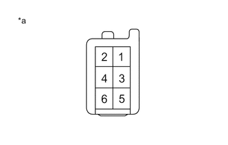
*a Front view of wire harness connector
(to Power Back Door Unit Assembly set LH )
Measure the resistance according to the value(s) in the table below.
Note
Make sure to connect the tester probes to the correct terminals. Connecting the probes to the wrong terminals can cause damage.
Standard Resistance Tester Connection Condition Specified Condition Positive (+) probe - 3 (DSV) - Negative (-) probe - 4 (DSG) Always 415.5 Ω or higher Result Proceed to OK NG
NG
REPLACE POWER BACK DOOR UNIT ASSEMBLY SET LH Click here
OK
-
-
INSPECT POWER BACK DOOR UNIT ASSEMBLY SET RH
-
Disconnect the Z19 power back door unit assembly set RH connector.
-
*a Front view of wire harness connector
(to Power Back Door Unit Assembly set RH )
Measure the resistance according to the value(s) in the table below.
Note
Make sure to connect the tester probes to the correct terminals. Connecting the probes to the wrong terminals can cause damage.
Standard Resistance Tester Connection Condition Specified Condition Positive (+) probe - 3 (DSV2) - Negative (-) probe - 4 (DSG2) Always 415.5 Ω or higher Result Proceed to OK NG
OK
REPLACE MULTIPLEX NETWORK DOOR ECU Click here
NG
REPLACE POWER BACK DOOR UNIT ASSEMBLY SET RH Click here
-
-
INSPECT POWER BACK DOOR SENSOR ASSEMBLY RH
-
Remove the power back door sensor assembly RH.
-
Inspect the power back door sensor assembly RH.
Result Proceed to OK NG
NG
REPLACE POWER BACK DOOR SENSOR ASSEMBLY RH Click here
OK
-
-
CHECK HARNESS AND CONNECTOR (POWER BACK DOOR SENSOR ASSEMBLY RH - MULTIPLEX NETWORK DOOR ECU)
-
Disconnect the Z14 power back door sensor assembly RH connector.
-
Disconnect the Z16 multiplex network door ECU connector.
-
Measure the resistance according to the value(s) in the table below.
Standard Resistance Tester Connection Condition Specified Condition Z14-1 (OSR) - Z16-6 (OSR) Always Below 1 Ω Z14-2 (OSRE) - Z16-24 (OSE) Always Below 1 Ω Z14-1 (OSR) or Z16-6 (OSR) - Body ground Always 10 kΩ or higher Z14-2 (OSRE) or Z16-24 (OSE) - Body ground Always 10 kΩ or higher Result Proceed to OK NG
OK
REPLACE MULTIPLEX NETWORK DOOR ECU Click here
NG
REPAIR OR REPLACE HARNESS OR CONNECTOR
-
-
INSPECT POWER BACK DOOR SENSOR ASSEMBLY LH
-
Remove the power back door sensor assembly LH.
-
Inspect the power back door sensor assembly LH.
Result Proceed to OK NG
NG
REPLACE POWER BACK DOOR SENSOR ASSEMBLY LH Click here
OK
-
-
CHECK HARNESS AND CONNECTOR (POWER BACK DOOR SENSOR ASSEMBLY LH - MULTIPLEX NETWORK DOOR ECU)
-
Disconnect the Z3 power back door sensor assembly LH connector.
-
Disconnect the Z16 multiplex network door ECU connector.
-
Measure the resistance according to the value(s) in the table below.
Standard Resistance Tester Connection Condition Specified Condition Z3-1 (OSL) - Z16-26 (OSL) Always Below 1 Ω Z3-2 (OSLE) - Z16-24 (OSE) Always Below 1 Ω Z3-1 (OSL) or Z16-26 (OSL) - Body ground Always 10 kΩ or higher Z3-2 (OSLE) or Z16-24 (OSE) - Body ground Always 10 kΩ or higher Result Proceed to OK NG
OK
REPLACE MULTIPLEX NETWORK DOOR ECU Click here
NG
REPAIR OR REPLACE HARNESS OR CONNECTOR
-