TELEMATICS SYSTEM(w/ Telematics Transceiver for G-BOOK) Received Voice Signal Circuit
WIRING DIAGRAM
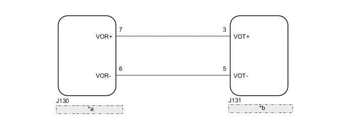
| *a | Radio Receiver Assembly |
| *b | Telematics Transceiver |
CAUTION / NOTICE / HINT
Note
Depending on the parts that are replaced during vehicle inspection or maintenance, performing initialization, registration or calibration may be needed. Refer to Precaution for G-BOOK.
PROCEDURE
-
CHECK HARNESS AND CONNECTOR (RADIO RECEIVER ASSEMBLY - TELEMATICS TRANSCEIVER)
-
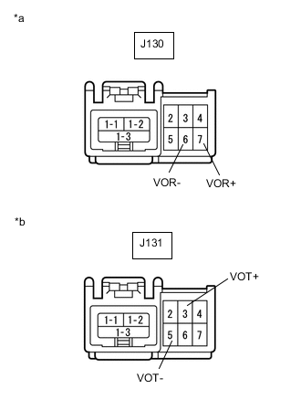
*a Front view of wire harness connector
(to Radio Receiver Assembly)
*b Front view of wire harness connector
(to Telematics Transceiver)
Disconnect the J130 radio receiver assembly connector.
-
Disconnect the J131 telematics transceiver connector.
-
Measure the resistance according to the value(s) in the table below.
Standard Resistance Tester Connection Condition Specified Condition J130-7 (VOR+) - J131-3 (VOT+) Always Below 1 Ω J130-6 (VOR-) - J131-5 (VOT-) Always Below 1 Ω J130-7 (VOR+) or J131-3 (VOT+) - Body ground Always 10 kΩ or higher J130-6 (VOR-) or J131-5 (VOT-) - Body ground Always 10 kΩ or higher Result Proceed to OK NG
NG 
REPAIR OR REPLACE HARNESS OR CONNECTOR
OK 
-
-
INSPECT TELEMATICS TRANSCEIVER
-
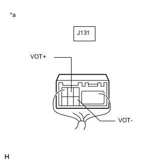
*a Component with harness connected
(Telematics Transceiver)
Check for pulses according to the value(s) in the table below.
Standard Tester Connection Condition Specified Condition J131-3 (VOT+) - Body ground Receiving a call while using the operator service A waveform synchronized with the received voice is output J131-5 (VOT-) - Body ground Receiving a call while using the operator service A waveform synchronized with the received voice is output Result Proceed to OK NG
OK
REPLACE RADIO RECEIVER ASSEMBLY Click here
NG
REPLACE TELEMATICS TRANSCEIVER Click here
-