TELEMATICS SYSTEM(w/ Telematics Transceiver), Diagnostic DTC:B15CB
| DTC Code | DTC Name |
|---|---|
| B15CB | Telematics Transceiver Antenna Disconnected |
DESCRIPTION
If an open or short circuit in the roof antenna assembly is detected continuously for 1 minute as a result of a terminal check performed by the telematics transceiver every minute after the engine switch is turned on (ACC), these DTCs will be stored.
| DTC No. | Detection Item | DTC Detection Condition | Trouble Area |
|---|---|---|---|
| B15CB | Telematics Transceiver Antenna Disconnected | The roof antenna assembly is not connected or has an open circuit |
|
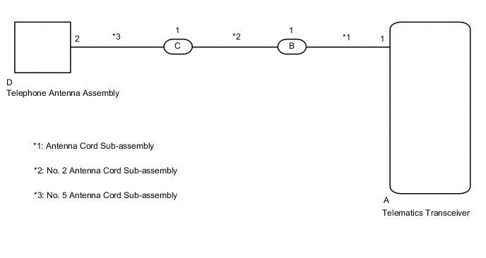
WIRING DIAGRAM
CAUTION / NOTICE / HINT
Note
Depending on the parts that are replaced during vehicle inspection or maintenance, performing initialization, registration or calibration may be needed. Refer to Precaution for G-BOOK.
PROCEDURE
-
CHECK DTC OUTPUT
-
Clear the DTCs.
Body Electrical > Navigation System > Clear DTCs -
Recheck for DTCs and check if the same DTC is output again.
Body Electrical > Navigation System > Trouble CodesResult Result Proceed to No DTCs are output. A DTCs are output. B
A 
USE SIMULATION METHOD TO CHECK Click here
B 
-
-
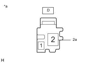
INSPECT TELEPHONE ANTENNA ASSEMBLY
-
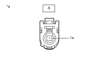
*a Component without harness connected
(Telephone Antenna Assembly)
Remove the telephone antenna assembly.
-
Measure the resistance according to the value(s) in the table below.
Standard Resistance Tester Connection Condition Specified Condition 2 - 2a Always 4 to 11 kΩ Result Proceed to OK NG
NG
REPLACE TELEPHONE ANTENNA ASSEMBLY Click here
OK
-
-
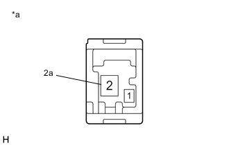
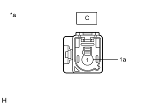
INSPECT NO. 5 ANTENNA CORD SUB-ASSEMBLY
-
*a Component without harness connected
(No. 5 Antenna Cord Sub-assembly)
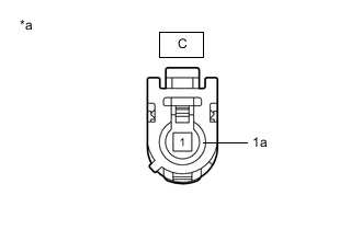
Disconnect the D No. 5 antenna assembly connector.
-
*a Component without harness connected
(No. 5 Antenna Cord Sub-assembly)
Disconnect the C No. 5 antenna cord sub-assembly connector.
-
Measure the resistance according to the value(s) in the table below.
Standard Resistance Tester Connection Condition Specified Condition D-2 - C-1 Always Below 1 Ω D-2 or C-1 - Body ground Always 10 kΩ or higher D-2a - C-1a Always Below 1 Ω D-2a or C-1a - Body ground Always 10 kΩ or higher Result Proceed to OK NG
NG
REPLACE NO. 5 ANTENNA CORD SUB-ASSEMBLY Click here
OK
-
-
INSPECT NO. 2 ANTENNA CORD SUB-ASSEMBLY
-
*a Component without harness connected
(No. 2 Antenna Cord Sub-assembly)
Disconnect the C No. 2 antenna cord sub-assembly connector.
-
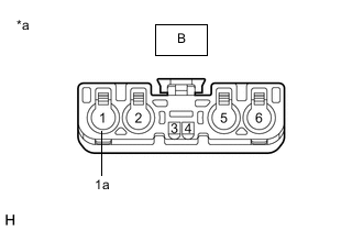
*a Component without harness connected
(No. 2 Antenna Cord Sub-assembly)
Disconnect the B No. 2 antenna cord sub-assembly connector.
-
Measure the resistance according to the value(s) in the table below.
Standard Resistance Tester Connection Condition Specified Condition C-1 - B-1 Always Below 1 Ω C-1 or B-1 - Body ground Always 10 kΩ or higher C-1a - B-1a Always Below 1 Ω C-1a or B-1a - Body ground Always 10 kΩ or higher Result Proceed to OK NG
NG
REPLACE NO. 2 ANTENNA CORD SUB-ASSEMBLY Click here
OK
-
-
INSPECT ANTENNA CORD SUB-ASSEMBLY
-
*a Component without harness connected
(Antenna Cord Sub-assembly)
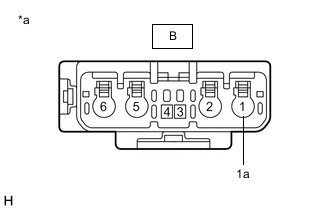
Disconnect the B antenna cord sub-assembly connector.
-
*a Component without harness connected
(Antenna Cord Sub-assembly)
Disconnect the A antenna cord sub-assembly connector.
-
Measure the resistance according to the value(s) in the table below.
Standard Resistance Tester Connection Condition Specified Condition B-1 - A-1 Always Below 1 Ω B-1 or A-1 - Body ground Always 10 kΩ or higher B-1a - A-1a Always Below 1 Ω B-1a or A-1a - Body ground Always 10 kΩ or higher Result Proceed to OK NG
NG
REPLACE ANTENNA CORD SUB-ASSEMBLY Click here
OK
-
-
REPLACE TELEMATICS TRANSCEIVER
-
Replace the telematics transceiver.
Result Proceed to NEXT
NEXT
-
-
CHECK DTC OUTPUT
-
Clear the DTCs.
Body Electrical > Navigation System > Clear DTCs -
Recheck for DTCs and check if the same DTC is output again.
Body Electrical > Navigation System > Trouble CodesResult Result Proceed to No DTCs are output. A DTCs are output. B
A
END
B
REPLACE RADIO RECEIVER ASSEMBLY Click here
-