NAVIGATION SYSTEM, Diagnostic DTC:B15C0, B15C1
| DTC Code | DTC Name |
|---|---|
| B15C0 | GPS Antenna Connection Malfunction(short) |
| B15C1 | GPS Antenna Connection Malfunction(break) |
DESCRIPTION
These DTCs are stored when a malfunction occurs in the navigation antenna assembly*1 or telephone antenna assembly*3.
| DTC No. | Detection Item | DTC Detection Condition | Trouble Area |
|---|---|---|---|
| B15C0 | GPS Antenna Connection Malfunction(short) | Navigation antenna assembly error*1 or Telephone antenna assembly error*3 |
|
| B15C1 | GPS Antenna Connection Malfunction(break) | Navigation antenna assembly power source malfunction*1 or Telephone antenna assembly power source malfunction*3 |
|
-
*1: w/o Heated Windshield Defroster System
-
*2: w/ Heated Windshield Defroster System with Telematics Transceiver
-
*3: w/ Heated Windshield Defroster System without Telematics Transceiver
CAUTION / NOTICE / HINT
Note
Depending on the parts that are replaced during vehicle inspection or maintenance, performing initialization, registration or calibration may be needed. Refer to Precaution for Navigation System.
PROCEDURE
-
CHECK DTC
-
Clear the DTCs.
Body Electrical > Navigation System > Clear DTCs -
Recheck for DTCs and check that no DTCs are output.
Body Electrical > Navigation System > Trouble CodesOK No DTCs are output. Result Result Proceed to OK (w/o Heated Windshield Defroster System) A OK (w/ Heated Windshield Defroster System without Manual (SOS) Switch) B OK (w/ Heated Windshield Defroster System with Manual (SOS) Switch) C NG D
B 
INSPECT NO. 6 ANTENNA CORD SUB-ASSEMBLY Click here
C
INSPECT ANTENNA DIVIDER Click here
D 
USE SIMULATION METHOD TO CHECK Click here
A 
-
-
INSPECT ANTENNA CORD SUB-ASSEMBLY
-
Remove the antenna cord sub-assembly.
-
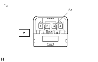
*a Component without harness connected
(Antenna Cord Sub-assembly)
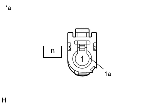
*a Component without harness connected
(Antenna Cord Sub-assembly)
Measure the resistance according to the value(s) in the table below.
Standard Resistance Tester Connection Condition Specified Condition A-3 - B-1 Always Below 1 Ω A-3a - B-1a Always Below 1 Ω A-3 or B-1 - Body ground Always 10 kΩ or higher Result Proceed to OK NG
NG
REPLACE ANTENNA CORD SUB-ASSEMBLY Click here
OK
-
-
INSPECT NAVIGATION ANTENNA ASSEMBLY
-
Remove the navigation antenna assembly.
-
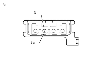
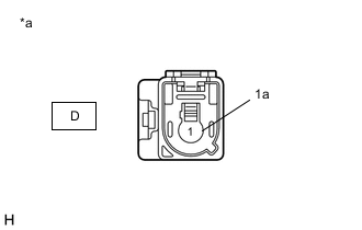
*a Component without harness connected
(Navigation Antenna Assembly)
Measure the resistance according to the value(s) in the table below.
Standard Resistance Tester Connection Condition Specified Condition 3 - 3a Always 50 to 500 Ω Result Proceed to OK NG
OK
REPLACE RADIO RECEIVER ASSEMBLY Click here
NG
REPLACE NAVIGATION ANTENNA ASSEMBLY Click here
-
-
INSPECT NO. 6 ANTENNA CORD SUB-ASSEMBLY
-
Remove the No. 6 antenna cord sub-assembly.
-
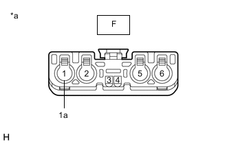
*a Component without harness connected
(No. 6 Antenna Cord Sub-assembly)
*a Component without harness connected
(No. 6 Antenna Cord Sub-assembly)
Measure the resistance according to the value(s) in the table below.
Standard Resistance Tester Connection Condition Specified Condition C-2 - D-2 Always Below 1 Ω C-2a - D-2a Always Below 1 Ω C-2 or D-2 - Body ground Always 10 kΩ or higher C-2a or D-2a - Body ground Always 10 kΩ or higher Result Proceed to OK NG
NG
REPLACE NO. 6 ANTENNA CORD SUB-ASSEMBLY Click here
OK
-
-
INSPECT NO. 2 ANTENNA CORD SUB-ASSEMBLY
-
Remove the No. 2 antenna cord sub-assembly.
-

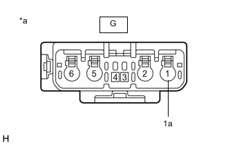
*a Component without harness connected
(No. 2 Antenna Cord Sub-assembly)
*a Component without harness connected
(No. 2 Antenna Cord Sub-assembly)
Measure the resistance according to the value(s) in the table below.
Standard Resistance Tester Connection Condition Specified Condition E-1 - F-1 Always Below 1 Ω E-1a - F-1a Always Below 1 Ω E-1 or F-1 - Body ground Always 10 kΩ or higher E-1a or F-1a - Body ground Always 10 kΩ or higher Result Proceed to OK NG
NG
REPLACE NO. 2 ANTENNA CORD SUB-ASSEMBLY Click here
OK
-
-
INSPECT ANTENNA CORD SUB-ASSEMBLY
-
Remove the antenna cord sub-assembly.
-
*a Component without harness connected
(Antenna Cord Sub-assembly)

*a Component without harness connected
(Antenna Cord Sub-assembly)
Measure the resistance according to the value(s) in the table below.
Standard Resistance Tester Connection Condition Specified Condition G-1 - H-1 Always Below 1 Ω G-1a - H-1a Always Below 1 Ω G-1 or H-1 - Body ground Always 10 kΩ or higher G-1a or H-1a - Body ground Always 10 kΩ or higher Result Proceed to OK NG
NG
REPLACE ANTENNA CORD SUB-ASSEMBLY Click here
OK
-
-
REPLACE TELEPHONE ANTENNA ASSEMBLY
-
Replace the telephone antenna assembly with a new or known good one.
-
Clear the DTCs.
Body Electrical > Telematics > Clear DTCs -
Recheck for DTCs and check that no DTCs are output.
Body Electrical > Telematics > Trouble CodesOK No DTCs are output. Result Proceed to OK NG
OK
END
NG
REPLACE RADIO RECEIVER ASSEMBLY Click here
-
-
INSPECT ANTENNA DIVIDER
-
Remove the Antenna divider.
-
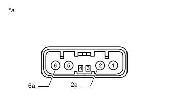
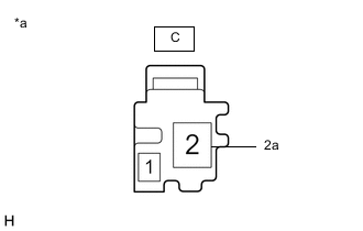
*a Component without harness connected
(Antenna Divider)
Measure the resistance according to the value(s) in the table below.
Standard Resistance Tester Connection Condition Specified Condition 2 - 6 Always 10 kΩ or higher 2 - 2a Always 243 to 267 Ω 6 - 6a Always 10 kΩ or higher Result Proceed to OK NG
NG
REPLACE ANTENNA DIVIDER Click here
OK
-
-
INSPECT ANTENNA CORD SUB-ASSEMBLY
-
Remove the antenna cord sub-assembly.
-
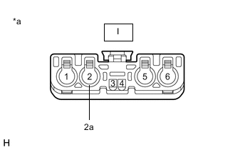
*a Component without harness connected
(Antenna Cord Sub-assembly)
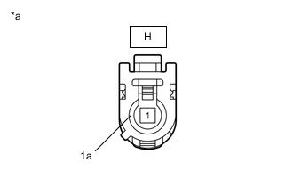
*a Component without harness connected
(Antenna Cord Sub-assembly)
Measure the resistance according to the value(s) in the table below.
Standard Resistance Tester Connection Condition Specified Condition I-2 - H-1 Always Below 1 Ω I-2a - H-1a Always Below 1 Ω I-2 or H-1 - Body ground Always 10 kΩ or higher I-2a or H-1a - Body ground Always 10 kΩ or higher Result Proceed to OK NG
NG
REPLACE ANTENNA CORD SUB-ASSEMBLY Click here
OK
-
-
REPLACE ANTENNA DIVIDER
-
Replace the antenna divider with a new or known good one.
-
Clear the DTCs.
Body Electrical > Telematics > Clear DTCs -
Recheck for DTCs and check that no DTCs are output.
Body Electrical > Telematics > Trouble CodesOK No DTCs are output. Result Proceed to OK NG
OK
END
NG
REPLACE RADIO RECEIVER ASSEMBLY Click here
-