REAR SEAT ENTERTAINMENT SYSTEM Display Signal Circuit between Multi-display Controller and Television Display
DESCRIPTION
This is the display signal circuit from the multi-display controller sub-assembly to each television display assembly.
WIRING DIAGRAM
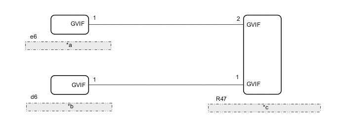
| *a | Television Display Assembly LH |
| *b | Television Display Assembly RH |
| *c | Multi-display Controller Sub-assembly |
PROCEDURE
-
REPLACE HARNESS AND CONNECTOR (MULTI-DISPLAY CONTROLLER SUB-ASSEMBLY - TELEVISION DISPLAY)
-
Replace the harness and connector with a new or known good one.
Result Proceed to OK NG
OK 
PROCEED TO NEXT SUSPECTED AREA SHOWN IN PROBLEM SYMPTOMS TABLE Click here
NG
REPAIR OR REPLACE HARNESS OR CONNECTOR
-