REAR SEAT ENTERTAINMENT SYSTEM AVC-LAN Circuit
DESCRIPTION
Each unit of the rear seat entertainment system connected to the AVC-LAN (communication bus) transmits switch signals through the AVC-LAN.
If a short to +B or short to ground occurs in the AVC-LAN, the rear seat entertainment system will not function normally because communication is not possible.
WIRING DIAGRAM
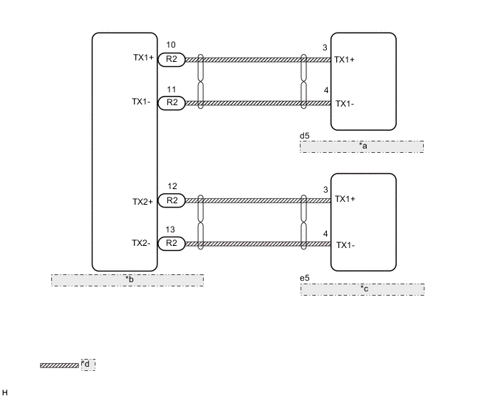
| *a | Television Display Assembly RH |
| *b | Multi-display Controller Sub-assembly |
| *c | Television Display Assembly LH |
| *d | AVC-LAN Communication Line |
CAUTION / NOTICE / HINT
Tech Tips
The multi-display controller sub-assembly is the master unit.
PROCEDURE
-
INSPECT MULTI-DISPLAY CONTROLLER SUB-ASSEMBLY
-
Remove the multi-display controller sub-assembly.
w/o Rear No. 2 Seat: Click here
w/ Rear No. 2 Seat: Click here
-
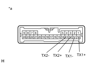
*a Component without harness connected
(Multi-display Controller Sub-assembly.)
Measure the resistance according to the value(s) in the table below.
Standard Resistance Tester Connection Condition Specified Condition 10 (TX1+) - 11 (TX1-) Always 60 to 80 Ω 12 (TX2+) - 13 (TX2-) Always 60 to 80 Ω Result Proceed to OK NG
NG 
REPLACE MULTI-DISPLAY CONTROLLER SUB-ASSEMBLY w/o Rear No. 2 Seat: Click here
REPLACE MULTI-DISPLAY CONTROLLER SUB-ASSEMBLY w/ Rear No. 2 Seat: Click hereOK 
-
-
CHECK HARNESS AND CONNECTOR (AVC-LAN CIRCUIT)
-
Disconnect the R2 multi-display controller sub-assembly connector.
-
Disconnect the e5 television display assembly LH connector.
-
Disconnect the d5 television display assembly RH connector.
-
Measure the resistance according to the value(s) in the table below.
Standard Resistance Tester Connection Condition Specified Condition R2-10 (TX1+) - d5-3 (TX1+) Always Below 1 Ω R2-11 (TX1-) - d5-4 (TX1-) Always Below 1 Ω R2-12 (TX2+) - e5-3 (TX1+) Always Below 1 Ω R2-13 (TX2-) - e5-4 (TX1-) Always Below 1 Ω R2-10 (TX1+) - Body ground Always 10 kΩ or higher R2-11 (TX1-) - Body ground Always 10 kΩ or higher R2-12 (TX2+) - Body ground Always 10 kΩ or higher R2-13 (TX2-) - Body ground Always 10 kΩ or higher Result Proceed to OK NG
NG
REPAIR OR REPLACE HARNESS OR CONNECTOR
OK
-
-
INSPECT MALFUNCTIONING PARTS
-
Disconnect and reconnect each slave unit one by one until the master unit returns to normal operation.
Tech Tips
-
Check all slave units.
-
If disconnecting a slave unit causes the master unit to return to normal operation, the slave unit is defective and should be replaced.
OK Master unit returns to normal operation. Result Proceed to OK NG -
OK
REPLACE MALFUNCTIONING PARTS
NG
REPLACE MULTI-DISPLAY CONTROLLER SUB-ASSEMBLY w/o Rear No. 2 Seat: Click here
REPLACE MULTI-DISPLAY CONTROLLER SUB-ASSEMBLY w/ Rear No. 2 Seat: Click here -