REAR SEAT ENTERTAINMENT SYSTEM TERMINALS OF ECU
Tech Tips
Check from the rear of the connector while it is connected to the components.
-
MULTI-DISPLAY CONTROLLER SUB-ASSEMBLY
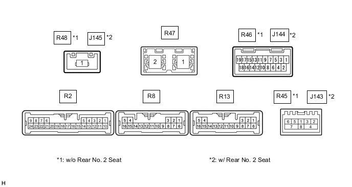
Terminal No. (Symbol) Wiring Color Terminal Description Condition Specification R2-2 (MUT1) - R13-14 (GND) GR - W-B Mute signal RSE playing
→ Source changed
Above 3.5 V
→ Below 1 V
R2-3 (HP1R) - R13-14 (GND) B - W-B RSE sound signal RSE playing A waveform synchronized with sound is output R2-4 (SLD5) - R13-14 (GND) Shield - W-B Shield ground Always Below 1 V R2-5 (HP1L) - R13-14 (GND) W - W-B RSE sound signal RSE playing A waveform synchronized with sound is output R2-6 (MUT2) - R13-14 (GND) L - W-B Mute signal RSE playing
→ Source changed
Above 3.5 V
→ Below 1 V
R2-7 (HP2R) - R13-14 (GND) G - W-B RSE sound signal RSE playing A waveform synchronized with sound is output R2-8 (SLD6) - R13-14 (GND) Shield - W-B Shield ground Always Below 1 V R2-9 (HP2L) - R13-14 (GND) R - W-B RSE sound signal RSE playing A waveform synchronized with sound is output R2-10 (TX1+) LG AVC-LAN communication signal - - R2-11 (TX1-) V AVC-LAN communication signal - - R2-12 (TX2+) R AVC-LAN communication signal - - R2-13 (TX2-) G AVC-LAN communication signal - - R2-19 (MUT3) - R13-14 (GND) Y - W-B Mute signal RSE playing
→ Source changed
Above 3.5 V
→ Below 1 V
R2-20 (MUT4) - Body ground P - Body ground Mute signal RSE playing
→ Source changed
Above 3.5 V
→ Below 1 V
R13-1 (+B) - R13-14 (GND) LA-R - W-B*1
R - W-B*2
Power source (+B) Always 11 to 14 V R13-2 (PWR2) - R13-14 (GND) SB - W-B Television display assembly LH power supply Engine switch on (IG) 11 to 14 V R13-3 (PWR1) - R13-14 (GND) L - W-B Television display assembly RH power supply Engine switch on (IG) 11 to 14 V R13-6 (+B2) - R13-14 (GND) LA-W - W-B*1
W - W-B*2
Power source (+B) Always 11 to 14 V R13-8 (VMTR) - R13-14 (GND) B - W-B Visual mute signal RSE playing
→ Source changed
Above 3.5 V
→ Below 1 V
R13-9 (MD0) - R13-14 (GND) V - W-B LH/RH display recognition signal Always Below 1 V R13-10 (GND2) - R13-14 (GND) LG - W-B Ground Always Below 1 V R13-11 (GND4) - Body ground B - Body ground Ground Always Below 1 V R13-12 (GND1) - R13-14 (GND) R - W-B Ground Always Below 1 V R13-13 (GND3) - Body ground G - Body ground Ground Always Below 1 V R13-14 (GND) - Body ground W-B - Body ground Ground Always Below 1 V R13-15 (GND5) - Body ground BR - Body ground Ground Always Below 1 V R8-4 (VMT1) - R13-14 (GND) P - W-B Visual mute signal Display operating
→ Source changed
Above 3.5 V
→ Below 1 V
R8-5 (VMT2) - R13-14 (GND) R - W-B Visual mute signal Display operating
→ Source changed
Above 3.5 V
→ Below 1 V
R45-2 (MI+)*1 B MOST communication signal - - R45-3 (MI-)*1 B MOST communication signal - - R45-4 (SLDI)*1 Shield - Body ground Shield ground - - R45-5 (MO+)*1 B MOST communication signal - - R45-6 (MO-)*1 B MOST communication signal - - R45-7 (SLDO)*1 Shield - Body ground Shield ground - - R45-8 (WUI) - R13-14 (GND)*1 W - W-B MOST communication wake up signal - - J143-2 (MI+)*2 B MOST communication signal - - J143-3 (MI-)*2 B MOST communication signal - - J143-4 (SLDI)*2 Shield - Body ground Shield ground - - J143-5 (MO+)*2 B MOST communication signal - - J143-6 (MO-)*2 B MOST communication signal - - J143-7 (SLDO)*2 Shield - Body ground Shield ground - - J143-8 (WUI) - R13-14 (GND)*2 W - W-B MOST communication wake up signal - - R48-1 (GVIF)*1 B Video signal (Digital) - - J145-1 (GVIF)*2 B Video signal (Digital) - - R47-1 (GVIF) B Video signal (Digital) - - R47-2 (GVIF) B Video signal (Digital) - - R46-2 (HDMI)*1 - Video signal (Digital) - - J144-2 (HDMI)*2 - Video signal (Digital) - -
-
*1: w/o Rear No. 2 Seat
-
*2: w/ Rear No. 2 Seat
-
-
TELEVISION DISPLAY ASSEMBLY LH

Terminal No. (Symbol) Wiring Color Terminal Description Condition Specification e5-2 (VMTR) - e5-9 (GND6) GR - V Visual mute signal RSE playing
→ Source changed
Above 3.5 V
→ Below 1 V
e5-3 (TX1+) P AVC-LAN communication signal - - e5-4 (TX1-) L AVC-LAN communication signal - - e5-6 (PWR1) - e5-9 (GND6) G - V Television display assembly LH power supply Display operating 11 to 14 V e5-7 (MUTE) - e5-9 (GND6) W - V Mute signal RSE playing
→ Source changed
Above 3.5 V
→ Below 1 V
e5-8 (IMTR) - e5-9 (GND6) SB - V Mute signal RSE playing
→ Source changed
Above 3.5 V
→ Below 1 V
e5-9 (GND6) - Body ground V - Body ground Ground Always Below 1 V e5-10 (GND4) - Body ground R - Body ground Ground Always Below 1 V e6-1 (GVIF) B Video signal (Digital) - - -
TELEVISION DISPLAY ASSEMBLY RH

Terminal No. (Symbol) Wiring Color Terminal Description Condition Specification d5-1 (MDO) - d5-10 (GND4) LG - R LH/RH display recognition signal Always Below 1 V d5-2 (VMTR) - d5-10 (GND4) GR - R Visual mute signal RSE playing
→ Source changed
Above 3.5 V
→ Below 1 V
d5-3 (TX1+) P AVC-LAN communication signal - - d5-4 (TX1-) L AVC-LAN communication signal - - d5-6 (PWR1) - d5-10 (GND4) G - R Television display assembly RH power supply Display operating 11 to 14 V d5-7 (MUTE) - d5-10 (GND4) W - R Mute signal RSE playing
→ Source changed
Above 3.5 V
→ Below 1 V
d5-8 (IMTR) - d5-10 (GND4) SB - R Mute signal RSE playing
→ Source changed
Above 3.5 V
→ Below 1 V
d5-9 (GND6) - Body ground V - Body ground Ground Always Below 1 V d5-10 (GND4) - Body ground R - Body ground Ground Always Below 1 V d6-1 (GVIF) B Video signal (Digital) - - -
RADIO RECEIVER ASSEMBLY