STEERING COLUMN ASSEMBLY INSTALLATION
PROCEDURE
-
ALIGN FRONT WHEELS FACING STRAIGHT AHEAD
-
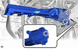
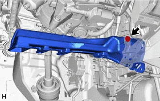
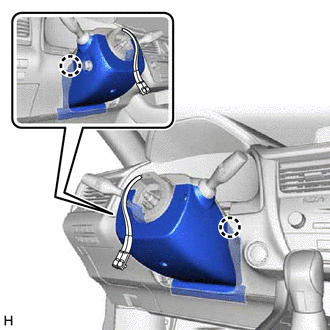
INSTALL STEERING COLUMN ASSEMBLY
Note
Make sure that the wire harness is not interfering with the steering column assembly.
-
Install the steering column assembly with the bolt and 2 nuts.
- Torque:
- 36 N*m { 367 kgf*cm, 27 ft.*lbf }
-
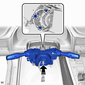
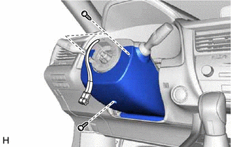
Connect each connector and engage each wire harness clamp to the steering column assembly.
-
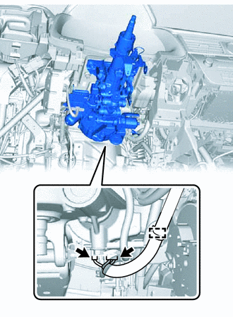
Connect the 2 connectors.
-
Engage the clamp.
-
-
INSTALL STEERING INTERMEDIATE SHAFT ASSEMBLY
-
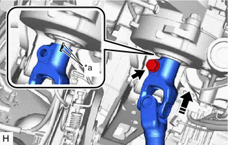
*a Matchmark Align the matchmarks on the steering intermediate shaft assembly and steering column assembly.
-
Install the steering intermediate shaft assembly to the steering column assembly.
-
Install a new bolt.
- Torque:
- 64 N*m { 653 kgf*cm, 47 ft.*lbf }
-
Tighten the bolt.
-
-
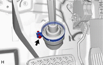
CONNECT STEERING INTERMEDIATE SHAFT ASSEMBLY
-
INSTALL STOP LIGHT SWITCH ASSEMBLY (for LHD)
-
INSTALL NO. 4 AIR DUCT SUB-ASSEMBLY
-
Engage the 3 claws to install a new No. 4 air duct sub-assembly.
-
Install the bolt.
- Torque:
- 9.8 N*m { 100 kgf*cm, 87 in.*lbf }
-
-
INSTALL FRONT NO. 1 CONSOLE BOX INSERT
-
INSTALL CONSOLE BOX ASSEMBLY
-
INSTALL CONSOLE REAR END PANEL SUB-ASSEMBLY
-
INSTALL MAYDAY BATTERY WITH BRACKET (w/ Telematics Transceiver for G-BOOK)
-
INSTALL CONSOLE PANEL SUB-ASSEMBLY
-
INSTALL SHIFT LEVER KNOB SUB-ASSEMBLY
-
INSTALL REMOTE TOUCH ASSEMBLY
-
INSTALL LOWER NO. 1 INSTRUMENT PANEL AIRBAG ASSEMBLY
-
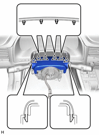
INSTALL TURN SIGNAL SWITCH ASSEMBLY WITH SPIRAL CABLE SUB-ASSEMBLY
Note
-
Do not replace the spiral cable with sensor sub-assembly with the battery connected and the engine switch on (IG).
-
Do not rotate the spiral cable with sensor sub-assembly without the steering wheel assembly installed, with the battery connected and the engine switch on (IG).
-
Ensure that the steering wheel assembly is installed and aligned straight when inspecting the steering sensor.
-

Install in this direction Engage the 3 claws to install the turn signal switch assembly with spiral cable sub-assembly to the steering column assembly.
-
Connect each connector to the turn signal switch assembly with spiral cable sub-assembly.
-
-
INSTALL UPPER STEERING COLUMN COVER
-
Engage the 6 clips to the upper steering column cover.
-
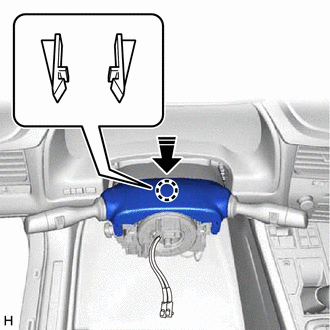
Install in this direction Engage the 2 claws to install the upper steering column cover.
-
-
INSTALL LOWER STEERING COLUMN COVER
-
Engage the 2 claws to install the lower steering column cover.
-
Install the 3 screws.
- Torque:
- 2.0 N*m { 20 kgf*cm, 18 in.*lbf }
-
-
ALIGN FRONT WHEELS FACING STRAIGHT AHEAD
-
INSPECT AND ADJUST SPIRAL CABLE WITH SENSOR SUB-ASSEMBLY
-
INSTALL STEERING WHEEL ASSEMBLY
-
CHECK STEERING WHEEL CENTER POINT
-
INSTALL HORN BUTTON ASSEMBLY
-
CUSTOMIZE POWER TILT AND POWER TELESCOPIC STEERING COLUMN SYSTEM
-
Set the auto tilt away function setting to the previous condition by changing the customize parameter.
-
-
PERFORM CALIBRATION OF TORQUE SENSOR ZERO POINT
-
ADJUST PARKING ASSIST MONITOR SYSTEM
w/o Parallel Parking Assist Function: Click here
w/ Parallel Parking Assist Function: Click here
-
ADJUST PANORAMIC VIEW MONITOR SYSTEM (w/ Panoramic View Monitor System)