HEATED STEERING WHEEL SYSTEM Steering Wheel does not Heat Up When Heated Steering Wheel Switch is Pressed
DESCRIPTION
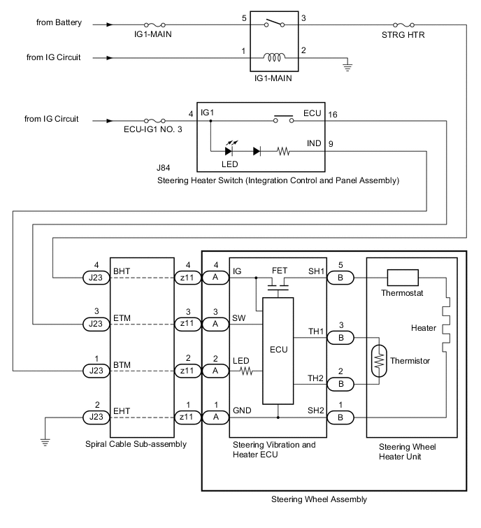
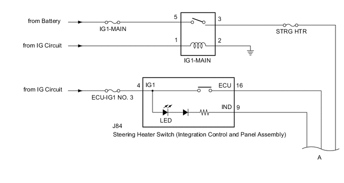
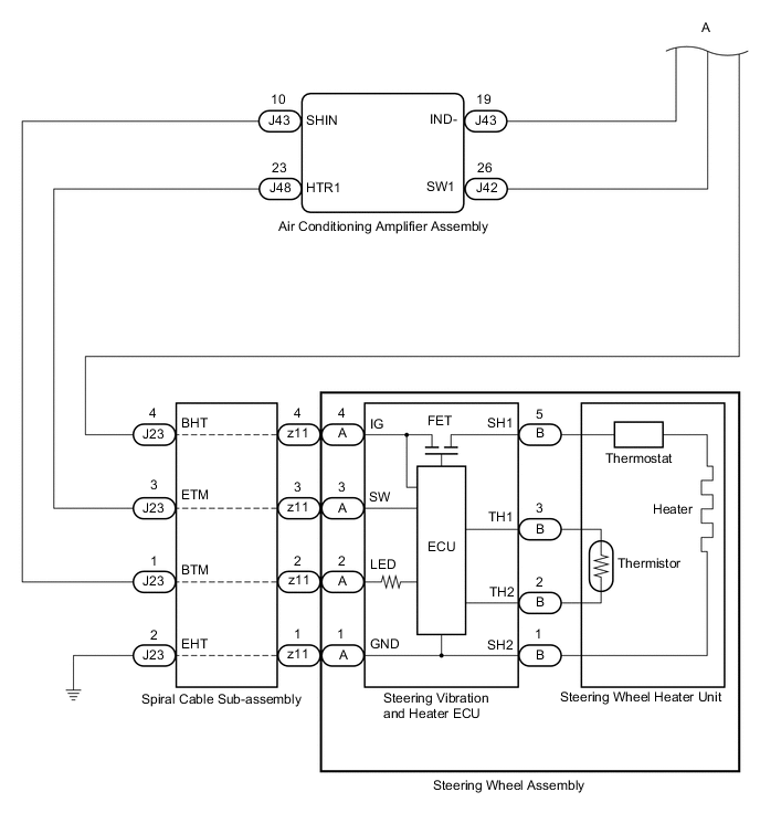
WIRING DIAGRAM
-
w/o Heated Windshield Defroster System
-
w/ Heated Windshield Defroster System
CAUTION / NOTICE / HINT
Tech Tips
-
Inspect the fuses for circuits related to this system before performing the following inspection procedure.
-
The steering vibration and heater ECU and steering wheel heater unit is built into the steering wheel assembly. Therefore, when the steering vibration and heater ECU steering wheel heater unit has a malfunction, replace the steering wheel assembly.
PROCEDURE
-
CHECK IG1-MAIN RELAY
-
Remove the IG1-MAIN relay from the No. 1 engine room relay block and No. 1 junction block assembly.
-
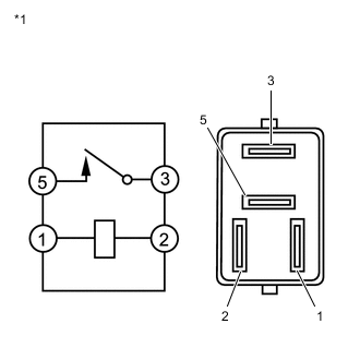
*1 IG1-MAIN Relay Measure the resistance according to the value(s) in the table below.
Standard Resistance Tester Connection Condition Specified Condition 3 - 5 Voltage is not applied between terminals 1 and 2 10 kΩ or higher Voltage is applied between terminals 1 and 2 Below 1 Ω Result Proceed to OK NG
NG 
REPLACE IG1-MAIN RELAY
OK 
-
-
CHECK HARNESS AND CONNECTOR (IG1-MAIN RELAY POWER SOURCE)
-
Remove the IG1-MAIN relay from the No. 1 engine room relay block and No. 1 junction block assembly.
-
Measure the voltage according to the value(s) in the table below.
Standard Voltage Tester Connection Condition Specified Condition 5 (IG1-MAIN relay) - Body ground Always 11 to 14 V 1 (IG1-MAIN relay) - Body ground Engine switch on (IG) 11 to 14 V -
Measure the resistance according to the value(s) in the table below.
Standard Resistance Tester Connection Condition Specified Condition 2 (IG1-MAIN relay) - Body ground Always Below 1 Ω Result Proceed to OK NG
NG
REPAIR OR REPLACE HARNESS OR CONNECTOR
OK
-
-
CHECK HARNESS AND CONNECTOR (STEERING HEATER SWITCH (INTEGRATION CONTROL AND PANEL ASSEMBLY) POWER SOURCE)
-
Disconnect the J84 steering heater switch (integration control and panel assembly) connector.
-
Measure the voltage according to the value(s) in the table below.
Standard Voltage Tester Connection Condition Specified Condition J84-4 (IG1) - Body ground Engine switch on (IG) 11 to 14 V Result Proceed to OK NG
NG
REPAIR OR REPLACE HARNESS OR CONNECTOR
OK
-
-
CHECK STEERING HEATER SWITCH (INTEGRATION CONTROL AND PANEL ASSEMBLY)
-
Disconnect the J84 steering heater switch (integration control and panel assembly) connector.
-
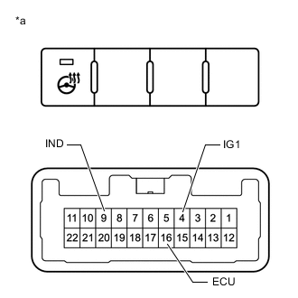
*a Component without harness connected
(Steering Heater Switch (Integration Control and Panel Assembly))
Measure the voltage according to the value(s) in the table below.
Tech Tips
As the circuit has a diode, perform the measurement in diode test mode, and do not mistake the polarity.
Standard Voltage Tester Connection(Positive (+) tester probe - Negative (-) tester probe) Condition Specified Condition J84-4 (IG1) - J84-9 (IND) Always Below 1.25 V J84-16 (ECU) - J84-9 (IND) Steering heater switch (integration control and panel assembly) is pushed Below 1.25 V -
Measure the resistance according to the value(s) in the table below.
Standard Resistance Tester Connection Condition Specified Condition J84-4 (IG1) - J84-16 (ECU) Steering heater switch (integration control and panel assembly) is pushed Below 1 Ω Steering heater switch (integration control and panel assembly) is not pushed 10 kΩ or higher Result Proceed to OK NG
NG
REPLACE STEERING HEATER SWITCH (INTEGRATION CONTROL AND PANEL ASSEMBLY) Click here
OK
-
-
CHECK HARNESS AND CONNECTOR (IG1-MAIN RELAY - SPIRAL CABLE SUB-ASSEMBLY)
-
Remove the IG1-MAIN relay from the No. 1 engine room relay block and No. 1 junction block assembly.
-
Disconnect the J23 spiral cable sub-assembly connector.
-
Measure the resistance according to the value(s) in the table below.
Standard Resistance Tester Connection Condition Specified Condition 3 (IG1-MAIN Relay) - J23-4 (BHT) Always Below 1 Ω 3 (IG1-MAIN Relay) or J23-4 (BHT) - Body ground Always 10 kΩ or higher Result Result Proceed to OK (w/o Heated Windshield Defroster System) A OK (w/ Heated Windshield Defroster System) B NG C
B 
CHECK HARNESS AND CONNECTOR (STEERING HEATER SWITCH (INTEGRATION CONTROL AND PANEL ASSEMBLY) - AIR CONDITIONING AMPLIFIER ASSEMBLY) Click here
C
REPAIR OR REPLACE HARNESS OR CONNECTOR
A
-
-
CHECK HARNESS AND CONNECTOR (STEERING HEATER SWITCH (INTEGRATION CONTROL AND PANEL ASSEMBLY) - SPIRAL CABLE SUB-ASSEMBLY)
-
Disconnect the J84 steering heater switch (integration control and panel assembly) connector.
-
Disconnect the J23 spiral cable sub-assembly connector.
-
Measure the resistance according to the value(s) in the table below.
Standard Resistance Tester Connection Condition Specified Condition J84-9 (IND) - J23-1 (BTM) Always Below 1 Ω J84-16 (ECU) - J23-3 (ETM) Always Below 1 Ω J84-9 (IND) or J23-1 (BTM) - Body ground Always 10 kΩ or higher J84-16 (ECU) or J23-3 (ETM) - Body ground Always 10 kΩ or higher Result Proceed to OK NG
NG
REPAIR OR REPLACE HARNESS OR CONNECTOR
OK
-
-
INSPECT SPIRAL CABLE SUB-ASSEMBLY
-
Check the connectors and cables of the spiral cable sub-assembly .
OK There are no defects such as scratches, cracks, dents or damage on the connectors or cables. -
Disconnect the J23 and z11 spiral cable sub-assembly connectors.
-
Measure the resistance according to the value(s) in the table below.

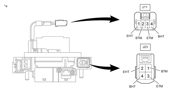
*a Component without harness connected
(Spiral Cable Sub-assembly)
- - Standard Resistance Tester Connection Condition Specified Condition z11-2 (BTM) - J23-1 (BTM) Always 3 Ω or less z11-3 (ETM) - J23-3 (ETM) Always 3 Ω or less z11-1 (EHT) - J23-2 (EHT) Always Below 0.1 Ω z11-4 (BHT) - J23-4 (BHT) Always Below 0.1 Ω Result Proceed to OK NG
NG
REPLACE SPIRAL CABLE SUB-ASSEMBLY Click here
OK
-
-
CHECK HARNESS AND CONNECTOR (SPIRAL CABLE SUB-ASSEMBLY BODY GROUND)
-
Disconnect the J23 spiral cable sub-assembly connector.
-
Measure the resistance according to the value(s) in the table below.
Standard Resistance Tester Connection Condition Specified Condition J23-2 (EHT) - Body ground Always Below 1 Ω Result Proceed to OK NG
OK
REPLACE STEERING WHEEL ASSEMBLY Click here
NG
REPAIR OR REPLACE HARNESS OR CONNECTOR
-
-
CHECK HARNESS AND CONNECTOR (STEERING HEATER SWITCH (INTEGRATION CONTROL AND PANEL ASSEMBLY) - AIR CONDITIONING AMPLIFIER ASSEMBLY)
-
Disconnect the J84 steering heater switch (integration control and panel assembly) connector.
-
Disconnect the J42 and J43 air conditioning amplifier assembly connector.
-
Measure the resistance according to the value(s) in the table below.
Standard Resistance Tester Connection Condition Specified Condition J84-9 (IND) - J43-19 (IND-) Always Below 1 Ω J84-16 (ECU) - J42-26 (SW1) Always Below 1 Ω J84-9 (IND) or J43-19 (IND-) - Body ground Always 10 kΩ or higher J84-16 (ECU) or J42-26 (SW1) - Body ground Always 10 kΩ or higher Result Proceed to OK NG
NG
REPAIR OR REPLACE HARNESS OR CONNECTOR
OK
-
-
CHECK HARNESS AND CONNECTOR (AIR CONDITIONING AMPLIFIER ASSEMBLY - SPIRAL CABLE SUB-ASSEMBLY)
-
Disconnect the J43 and J48 air conditioning amplifier assembly connector.
-
Disconnect the J23 spiral cable sub-assembly connector.
-
Measure the resistance according to the value(s) in the table below.
Standard Resistance Tester Connection Condition Specified Condition J43-10 (SHIN) - J23-1 (BTM) Always Below 1 Ω J48-23 (HTR1) - J23-3 (ETM) Always Below 1 Ω J43-10 (SHIN) or J23-1 (BTM) - Body ground Always 10 kΩ or higher J48-23 (HTR1) or J23-3 (ETM) - Body ground Always 10 kΩ or higher Result Proceed to OK NG
NG
REPAIR OR REPLACE HARNESS OR CONNECTOR
OK
-
-
INSPECT SPIRAL CABLE SUB-ASSEMBLY
-
Check the connectors and cables of the spiral cable sub-assembly .
OK There are no defects such as scratches, cracks, dents or damage on the connectors or cables. -
Disconnect the J23 and z11 spiral cable sub-assembly connectors.
-
Measure the resistance according to the value(s) in the table below.
*a Component without harness connected
(Spiral Cable Sub-assembly)
- - Standard Resistance Tester Connection Condition Specified Condition z11-2 (BTM) - J23-1 (BTM) Always 3 Ω or less z11-3 (ETM) - J23-3 (ETM) Always 3 Ω or less z11-1 (EHT) - J23-2 (EHT) Always Below 0.1 Ω z11-4 (BHT) - J23-4 (BHT) Always Below 0.1 Ω Result Proceed to OK NG
NG
REPLACE SPIRAL CABLE SUB-ASSEMBLY Click here
OK
-
-
CHECK HARNESS AND CONNECTOR (SPIRAL CABLE SUB-ASSEMBLY BODY GROUND)
-
Disconnect the J23 spiral cable sub-assembly connector.
-
Measure the resistance according to the value(s) in the table below.
Standard Resistance Tester Connection Condition Specified Condition J23-2 (EHT) - Body ground Always Below 1 Ω Result Proceed to OK NG
NG
REPAIR OR REPLACE HARNESS OR CONNECTOR
OK
-
-
INSPECT AIR CONDITIONING AMPLIFIER ASSEMBLY
-
Measure the voltage according to the value(s) in the table below.
Tech Tips
Perform the inspection from the harness side with the connectors connected.
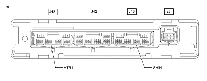
*a Component with harness connected
(Air Conditioning Amplifier Assembly)
- - Standard Voltage Tester Connection Condition Specified Condition J43-10 (SHIN) - Body ground Steering heater switch (integration control and panel assembly) is pushed Below 3 V J48-23 (HTR1) - Body ground Steering heater switch (integration control and panel assembly) is pushed 11 to 14 V for 0.08 seconds after heater switch (integration control and panel assembly) is turned on then below 1 V Result Proceed to OK NG
OK
REPLACE STEERING WHEEL ASSEMBLY Click here
NG
REPLACE AIR CONDITIONING AMPLIFIER ASSEMBLY
-