VACUUM PUMP(for 2GR-FKS) INSTALLATION
PROCEDURE
-
INSTALL VACUUM PUMP ASSEMBLY
-
When using a new vacuum pump assembly:
-
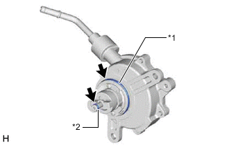
*1 No. 2 O-ring *2 No. 3 O-ring 
Engine oil Apply engine oil to the No. 2 O-ring and No. 3 O-ring which are installed to a new vacuum pump assembly.
-
-
When reusing the vacuum pump assembly:
-
*1 No. 2 O-ring *2 No. 3 O-ring Engine oil Apply engine oil to a new No. 2 O-ring and No. 3 O-ring and install them to the vacuum pump assembly.
-
-
Apply engine oil to the inner surface of the installation hole.
-
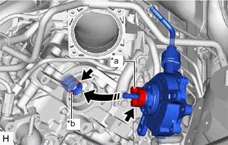
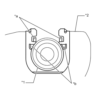
*a Coupling Teeth *b Groove Install the vacuum pump assembly so that the oil pipe engages with the hole of the camshaft and the coupling teeth with the grooves on the camshaft tip.
Note
-
Ensure that the vacuum pump assembly is installed securely.
-
Be careful not to pinch the O-ring.
-
-
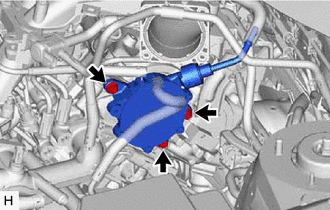
Install the vacuum pump assembly with the 3 bolts.
- Torque:
- 21 N*m { 214 kgf*cm, 15 ft.*lbf }
Note
After installation, check that there are no gaps between the matching surfaces and that the vacuum pump assembly is not installed at an angle.
-
-
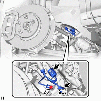
INSTALL ENGINE WIRE
-
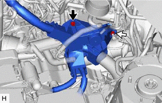
Bolt 
Nut Install the engine wire with the bolt and nut.
- Torque:
- 8.35 N*m { 85 kgf*cm, 74 in.*lbf }
-
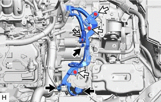
Connector Bolt 
Nut Install the 3 bolts and nut.
- Torque:
- Bolt
- 19.1 N*m { 195 kgf*cm, 14 ft.*lbf }
- Nut
- 9.8 N*m { 100 kgf*cm, 87 in.*lbf }
-
Connect the 3 connectors.
-
Install the 2 nuts.
- Torque:
- 8.35 N*m { 85 kgf*cm, 74 in.*lbf }
-
Engage the 2 clamps.
-
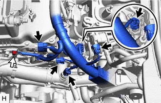
Connector Bolt Install the bolt.
- Torque:
- 8.35 N*m { 85 kgf*cm, 74 in.*lbf }
-
Connect the 5 connectors.
-
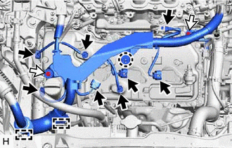
Connector Bolt Install the 2 bolts.
- Torque:
- 8.35 N*m { 85 kgf*cm, 74 in.*lbf }
-
Engage the 2 clamps and claw.
-
Connect the 8 connectors.
-
Connector Bolt Install the bolt.
- Torque:
- 8.35 N*m { 85 kgf*cm, 74 in.*lbf }
-
Engage the clamp.
-
Connect the 2 connectors.
-
-
INSTALL NO. 2 ENGINE UNDER COVER
-
CONNECT VACUUM HOSE SUB-ASSEMBLY
-
Connect the vacuum hose sub-assembly.
-
-
CONNECT HEATER WATER HOSE
-
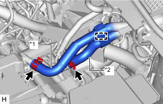
*1 Inlet Heater Water Hose *2 Outlet Heater Water Hose Connect the inlet heater water hose and outlet heater water hose, and slide the 2 clips to secure them.
-
Engage the clamp.
-
-
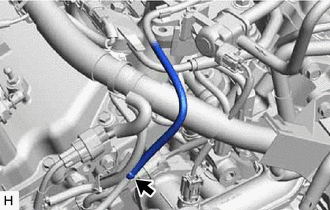
CONNECT VENTILATION HOSE
-
Connect the ventilation hose, and slide the clip to secure it.
-
-
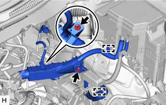
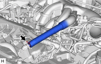
CONNECT AIR TUBE
-
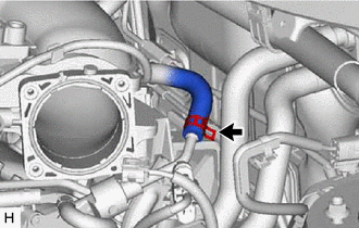
Connect the air tube to the vacuum pump assembly, and slide the clip to secure it.
-
-
INSTALL TRANSMISSION CONTROL CABLE ASSEMBLY
-
Install a new clip to the No. 1 transmission control cable bracket.
-
*1 Transmission Control Cable Assembly *2 No. 1 Transmission Control Cable Bracket *a Claw (A) *b Claw (B) Connect the transmission control cable assembly to the No. 1 transmission control cable bracket.
Note
-
Make sure that the claws (A) of the clip are securely fit into the bracket holes.
-
Make sure that the transmission control cable assembly is securely installed inside of the claws (B) of the clip.
-
-
Connect the transmission control cable assembly to the transmission control shaft lever with the nut.
- Torque:
- 12 N*m { 122 kgf*cm, 9 ft.*lbf }
-
-
INSTALL AIR CLEANER BRACKET
-
INSTALL AIR CLEANER CASE SUB-ASSEMBLY
-
INSTALL AIR CLEANER FILTER ELEMENT SUB-ASSEMBLY
-
INSTALL INLET AIR CLEANER ASSEMBLY
-
INSTALL V-BANK COVER SUB-ASSEMBLY
-
INSTALL COOL AIR INTAKE DUCT SEAL
-
INSTALL FRONT WHEEL LH
-
CONNECT CABLE TO NEGATIVE BATTERY TERMINAL
Note
When disconnecting the cable, some systems need to be initialized after the cable is reconnected.
-
INSTALL THROTTLE BODY WITH MOTOR ASSEMBLY
-
INSPECT VACUUM PUMP OPERATION