VEHICLE STABILITY CONTROL SYSTEM Brake Hold Standby Indicator Light Circuit
DESCRIPTION
When the brake hold switch (electric parking brake switch assembly) is turned on with the engine switch turned on (IG), the brake hold standby indicator light illuminates when brake hold operation is possible.
WIRING DIAGRAM
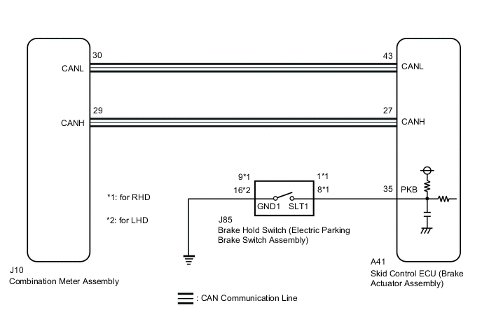
CAUTION / NOTICE / HINT
Note
When replacing the skid control ECU (brake actuator assembly), perform zero point calibration and store system information.
PROCEDURE
-
PRE-CHECK
-
If the brake hold standby indicator light does not illuminate even though the brake hold switch (electric parking brake switch assembly) is pushed, check that the brake hold function operation conditions are met.
-
The driver side door is closed.
-
The driver side seat belt is fastened.
-
The system is normal.
Result Proceed to NEXT -
NEXT 
-
-
CHECK CAN COMMUNICATION SYSTEM
-
Check if CAN communication system DTCs are output.
Result Result Proceed to DTCs are not output. A DTCs are output. B
B 
CHECK CAN COMMUNICATION SYSTEM Click here
A
-
-
CHECK IF BRAKE ACTUATOR ASSEMBLY CONNECTOR IS SECURELY CONNECTED
-
Check if the skid control ECU (brake actuator assembly) connector is securely connected.
OK The connector is securely connected. Result Proceed to OK NG
NG
CONNECT CONNECTOR TO BRAKE ACTUATOR ASSEMBLY CORRECTLY
OK
-
-
INSPECT COMBINATION METER ASSEMBLY
-
Connect the GTS to the DLC3.
-
Turn the engine switch off.
-
Perform the Active Test of the combination meter assembly (meter CPU) using the GTS.
Body Electrical > Combination Meter > Active TestTester Display Indicat. Brake Hold -
Check the combination meter assembly.
OK The brake hold standby indicator light turns on or off in accordance with the GTS operation. Result Proceed to OK NG
NG
INSPECT METER / GAUGE SYSTEM Click here
OK
-
-
PERFORM ACTIVE TEST USING GTS (BRAKE HOLD STANDBY INDICATOR LIGHT)
-
Turn the engine switch on (IG).
-
Select the Active Test on the GTS.
Chassis > ABS/VSC/TRC/EPB > Active TestTester Display Measurement Item Control Range Diagnostic Note BH Standby Light Brake hold standby indicator light Indicator light ON/OFF Observe combination meter assembly
Vehicle condition: Vehicle stopped
Chassis > ABS/VSC/TRC/EPB > Active TestTester Display BH Standby Light -
Select the Data List on the GTS.
Chassis > ABS/VSC/TRC/EPB > Data ListTester Display Measurement Item Range Normal Condition Diagnostic Note BH Standby Light Brake hold standby indicator light ON or OFF ON: Indicator light on
OFF: Indicator light off
-
Chassis > ABS/VSC/TRC/EPB > Data ListTester Display BH Standby Light -
Check the operating condition of the brake hold standby indicator light when operating it using the GTS.
Result Result Proceed to Brake hold standby indicator light in the Data List does not change using the Active Test. A Brake hold standby indicator light in the Data List turns ON/OFF using the Active Test. B Tech Tips
If troubleshooting has been carried out according to Problem Symptoms Table, refer back to the table and proceed to the next step before replacing parts.
A
REPLACE BRAKE ACTUATOR ASSEMBLY Click here
B
-
-
INSPECT ELECTRIC PARKING BRAKE SWITCH ASSEMBLY
-
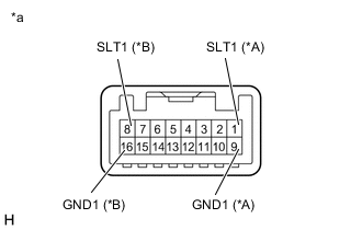
*A for LHD *B for RHD *a Component without harness connected
(Brake Hold Switch (Electric Parking Brake Switch Assembly))
Turn the engine switch off.
-
Disconnect the J85 brake hold switch (electric parking brake switch assembly) connector.
-
Measure the resistance according to the value(s) in the table below.
Standard Resistance for LHD Tester Connection Condition Specified Condition 1 (SLT1) - 9 (GND1) Switch pushed Below 1 Ω 1 (SLT1) - 9 (GND1) Switch not pushed 10 kΩ or higher for RHD Tester Connection Condition Specified Condition 8 (SLT1) - 16 (GND1) Switch pushed Below 1 Ω 8 (SLT1) - 16 (GND1) Switch not pushed 10 kΩ or higher Result Proceed to OK NG
NG
REPLACE ELECTRIC PARKING BRAKE SWITCH ASSEMBLY Click here
OK
-
-
CHECK HARNESS AND CONNECTOR (BRAKE ACTUATOR ASSEMBLY - ELECTRIC PARKING BRAKE SWITCH ASSEMBLY)
-
Disconnect the A41 skid control ECU (brake actuator assembly) connector.
-
Measure the resistance according to the value(s) in the table below.
Standard Resistance for LHD Tester Connection Condition Specified Condition A41-35 (PKB) - J85-1 (SLT1) Always Below 1 Ω A41-35 (PKB) or J85-1 (SLT1) - Body ground Always 10 kΩ or higher J85-9 (GND1) - Body ground Always Below 1 Ω for RHD Tester Connection Condition Specified Condition A41-35 (PKB) - J85-8 (SLT1) Always Below 1 Ω A41-35 (PKB) or J85-8 (SLT1) - Body ground Always 10 kΩ or higher J85-16 (GND1) - Body ground Always Below 1 Ω Result Proceed to OK NG Tech Tips
If troubleshooting has been carried out according to Problem Symptoms Table, refer back to the table and proceed to the next step before replacing parts.
OK
REPLACE BRAKE ACTUATOR ASSEMBLY Click here
NG
REPAIR OR REPLACE HARNESS OR CONNECTOR
-