VEHICLE STABILITY CONTROL SYSTEM, Diagnostic DTC:C1381

| DTC Code | DTC Name |
|---|---|
| C1381 | Acceleration Sensor Power Supply Voltage Malfunction |
DESCRIPTION
-
The skid control ECU (brake actuator assembly) receives signals from the yaw rate and acceleration sensor (airbag sensor assembly) via the CAN communication system.
The airbag sensor assembly has a built-in yaw rate and acceleration sensor and detects the vehicle's condition using 2 circuits (GL1, GL2).
If there is trouble in the bus lines between the yaw rate and acceleration sensor (airbag sensor assembly) and the CAN communication system, the DTC U0124 (Lost Communication with Lateral Acceleration Sensor Module) is output.
The DTCs are also output when the calibration has not been completed.
for Optitron Meter Type:
-
The skid control ECU (brake actuator assembly) receives signals from the yaw rate and acceleration sensor via the CAN communication system.
If there is trouble in the bus lines between the yaw rate and acceleration sensor and the CAN communication system, the DTC U0124 (Lost Communication with Lateral Acceleration Sensor Module) is output.
The DTCs are also output when the calibration has not been completed.
for TFT Meter Type:
| DTC No. | Detection Item | DTC Detection Condition | Trouble Area | Note |
|---|---|---|---|---|
| C1381 | Acceleration Sensor Power Supply Voltage Malfunction | At a vehicle speed of more than 3 km/h (2 mph), the acceleration sensor power source malfunction signal is received for 10 seconds or more. |
|
- |
WIRING DIAGRAM
Figure 1. for Optitron Meter Type:
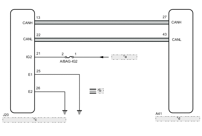
| *a | from IG Circuit |
| *b | CAN Communication Line |
| *c | Yaw Rate and Acceleration Sensor (Airbag Sensor Assembly) |
| *d | Skid Control ECU (Brake Actuator Assembly) |
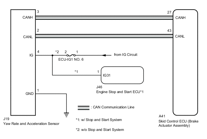
Figure 2. for TFT Meter Type:
CAUTION / NOTICE / HINT
Note
-
When replacing the yaw rate and acceleration sensor (airbag sensor assembly), perform zero point calibration and store system information (for optitron meter type).
When replacing the yaw rate and acceleration sensor, perform zero point calibration and store system information (for TFT meter type).
-
Inspect the fuses for circuits related to this system before performing the following procedure (w/o Stop and Start System).
PROCEDURE
-
CHECK VEHICLE
-
Check the combination meter assembly.
Result Result Proceed to for optitron meter type A for TFT meter type B
B 
CHECK TERMINAL VOLTAGE (IG2 TERMINAL) Click here
A 
-
-
CHECK TERMINAL VOLTAGE (IG2 TERMINAL)
-
Turn the engine switch off.
-
Disconnect the cable from the negative (-) battery terminal, and wait for at least 90 seconds.
-
Make sure that there is no looseness at the locking part and the connecting part of the connector.
-
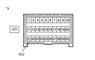
*a Front view of wire harness connector
(to Yaw Rate and Acceleration Sensor (Airbag Sensor Assembly))
Disconnect the J20 yaw rate and acceleration sensor (airbag sensor assembly) connector.
-
Connect the cable to the negative (-) battery terminal, and wait for at least 2 seconds.
-
Turn the engine switch on (IG).
-
Operate all the components of the electrical system (defogger, wipers, headlights, heater blower, etc.).
-
Measure the voltage according to the value(s) in the table below.
Standard Voltage Tester Connection Condition Specified Condition J20-21 (IG2) - Body ground Engine switch on (IG) 8 to 16 V Result Proceed to OK NG
NG 
REPAIR OR REPLACE HARNESS OR CONNECTOR (IG2 CIRCUIT)
OK
-
-
CHECK HARNESS AND CONNECTOR (GND TERMINAL)
-
Turn the engine switch off.
-
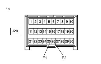
*a Front view of wire harness connector
(to Yaw Rate and Acceleration Sensor (Airbag Sensor Assembly))
Measure the resistance according to the value(s) in the table below.
Standard Resistance Tester Connection Condition Specified Condition J20-25 (E1) - Body ground Always Below 1 Ω J20-26 (E2) - Body ground Always Below 1 Ω Result Proceed to OK NG
NG
REPAIR OR REPLACE HARNESS OR CONNECTOR (GND CIRCUIT)
OK
-
-
RECONFIRM DTC
-
Reconnect the J20 yaw rate and acceleration sensor (airbag sensor assembly) connector.
-
Clear the DTC.
Chassis > ABS/VSC/TRC/EPB > Clear DTCs -
Turn the engine switch off.
-
Start the engine.
-
Perform a road test.
-
Check if the same DTC is recorded.
Chassis > ABS/VSC/TRC/EPB > Trouble CodesResult Result Proceed to DTC C1381 is not output. A DTC C1381 is output. B Tech Tips
If troubleshooting has been carried out according to Problem Symptoms Table, refer back to the table and proceed to the next step before replacing parts.
A
USE SIMULATION METHOD TO CHECK Click here
B
REPLACE AIRBAG SENSOR ASSEMBLY Click here
-
-
CHECK TERMINAL VOLTAGE (IG2 TERMINAL)
-
Turn the engine switch off.
-
Disconnect the cable from the negative (-) battery terminal, and wait for at least 90 seconds.
-
Make sure that there is no looseness at the locking part and the connecting part of the connector.
-
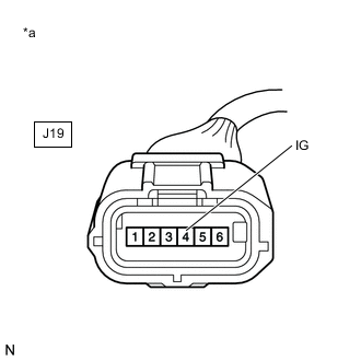
*a Front view of wire harness connector
(to Yaw Rate and Acceleration Sensor)
Disconnect the J19 yaw rate and acceleration sensor connector.
-
Connect the cable to the negative (-) battery terminal, and wait for at least 2 seconds.
-
Turn the engine switch on (IG).
-
Operate all the components of the electrical system (defogger, wipers, headlights, heater blower, etc.).
-
Measure the voltage according to the value(s) in the table below.
Standard Voltage Tester Connection Condition Specified Condition J19-4 (IG) - Body ground Engine switch on (IG) 8 to 16 V Result Result Proceed to OK A NG (w/o Stop and Start System) B NG (w/ Stop and Start System) C
B
REPAIR OR REPLACE HARNESS OR CONNECTOR (IG2 CIRCUIT)
C
INSPECT STOP AND START SYSTEM (BACKUP BOOST CONVERTER CIRCUIT) Click here
A
-
-
CHECK HARNESS AND CONNECTOR (GND TERMINAL)
-
Turn the engine switch off.
-
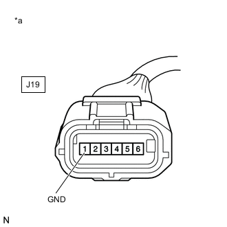
*a Front view of wire harness connector
(to Yaw Rate and Acceleration Sensor)
Measure the resistance according to the value(s) in the table below.
Standard Resistance Tester Connection Condition Specified Condition J19-1 (GND) - Body ground Always Below 1 Ω Result Proceed to OK NG
NG
REPAIR OR REPLACE HARNESS OR CONNECTOR (IG2 CIRCUIT)
OK
-
-
RECONFIRM DTC
-
Reconnect the J19 yaw rate and acceleration sensor connector.
-
Clear the DTC.
Chassis > ABS/VSC/TRC/EPB > Clear DTCs -
Turn the engine switch off.
-
Start the engine.
-
Perform a road test.
-
Check if the same DTC is recorded.
Chassis > ABS/VSC/TRC/EPB > Trouble CodesResult Result Proceed to DTC C1381 is not output. A DTC C1381 is output. B Tech Tips
If troubleshooting has been carried out according to Problem Symptoms Table, refer back to the table and proceed to the next step before replacing parts.
A
USE SIMULATION METHOD TO CHECK Click here
B
REPLACE YAW RATE AND ACCELERATION SENSOR Click here
-