STEERING KNUCKLE REMOVAL
CAUTION / NOTICE / HINT
The necessary procedures (adjustment, calibration, initialization, or registration) that must be performed after parts are removed and installed, or replaced during steering knuckle removal/installation are shown below.
| Replaced Part or Performed Procedure | Necessary Procedure | Effect/Inoperative Function when Necessary Procedure not Performed | Link |
|---|---|---|---|
| Front wheel alignment adjustment |
|
|
Tech Tips
-
Use the same procedure for the RH side and LH side.
-
The following procedure is for the LH side.
PROCEDURE
-
REMOVE FRONT AXLE ASSEMBLY
-
REMOVE FRONT LOWER BALL JOINT ASSEMBLY
-
REMOVE STEERING KNUCKLE
-
Secure the front axle assembly between aluminum plates in a vise.
Note
Do not overtighten the vise.
-
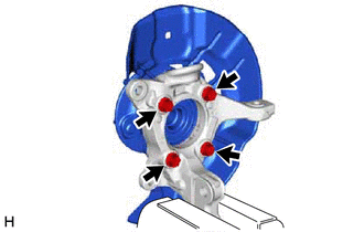
Remove the 4 bolts, front axle hub sub-assembly and front disc brake dust cover from the steering knuckle.
Note
-
Do not drop the front axle hub sub-assembly.
-
Be careful not to damage the speed sensor rotor or contact surfaces.
-
Do not allow foreign matter to contact the speed sensor rotor or contact surfaces.
-
-