PROPELLER SHAFT ASSEMBLY INSTALLATION

PROCEDURE
-
TEMPORARILY TIGHTEN PROPELLER WITH CENTER BEARING SHAFT ASSEMBLY
-

Remove SST from the transfer assembly.
-
Insert the propeller with center bearing shaft assembly into the transfer assembly.
Note
-
Be careful not to damage the transfer extension housing type T oil seal.
-
Be careful not to damage the universal joint boot when installing the propeller with center bearing shaft assembly.
-
-

*a Matchmark Align the matchmarks on the electro magnetic control coupling sub-assembly and propeller with center bearing shaft assembly.
-

Temporarily install the 4 nuts and 4 washers.
Note
Do not apply grease to the 4 bolts, 4 nuts or 4 washers.
-

Temporarily install the propeller with center bearing shaft assembly with the 4 bolts, and 4 center No. 2 support bearing washers.
Note
-
Reuse the center No. 2 support bearing washers.
-
Do not apply grease to the 4 bolts or 4 center No. 2 support bearing washers.
-
-
Fully tighten the 4 nuts.
- Torque:
- 73.5 N*m { 749 kgf*cm, 54 ft.*lbf }
-
-
FULLY TIGHTEN PROPELLER WITH CENTER BEARING SHAFT ASSEMBLY
-

*a Piece of Cloth Remove the piece of cloth or equivalent from the universal joint flange.
-
Using a 6 mm hexagon socket wrench, fully tighten the 6 cross groove joint set bolts.
- Torque:
- 26 N*m { 265 kgf*cm, 19 ft.*lbf }
-
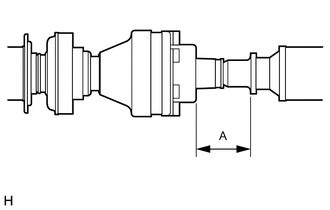
With the vehicle unloaded, adjust the distance (A) between the rear side of the cover and shaft as shown in the illustration.
Distance (A) 57.5 to 58.5 mm (2.27 to 2.30 in.) -
With the vehicle unloaded, adjust the front and rear distance (A) between the edge surface of the center No. 2 support bearing assembly and the edge surface of the cushion respectively as shown in the illustration, and then tighten the bolts.
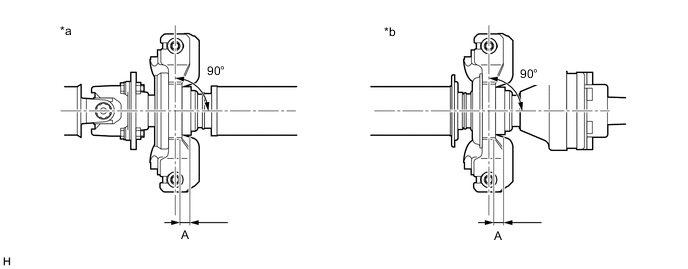
*a Center No. 2 Support Bearing Assembly (for Front Side) *b Center No. 2 Support Bearing Assembly (for Rear Side) Distance (A) 11.5 to 13.5 mm (0.453 to 0.531 in.) -
Fully tighten the 4 bolts.
- Torque:
- 36.8 N*m { 375 kgf*cm, 27 ft.*lbf }
-
Check that the center line of the bracket is at a right angle to the shaft axial direction.
-
-
INSPECT AND ADJUST TRANSFER OIL
-
INSPECT AND ADJUST JOINT ANGLE
Note
Measure the joint angle when the vehicle is raised using a four-post lift or when using a pit.
Tech Tips
If any vibration or noise occurs, perform the joint angle check as follows and replace the center No. 2 support bearing washers with ones of the correct thickness.
-
Stabilize the propeller shaft and differential.
-
Turn the propeller shaft several times by hand to stabilize the center support bearings.
-
Using a jack, raise and lower the differential to stabilize the differential mounting cushion.
-
-
Check the No. 1 and No. 4 joint angles.
*a No. 1 Joint Angle *b No. 4 Joint Angle
-
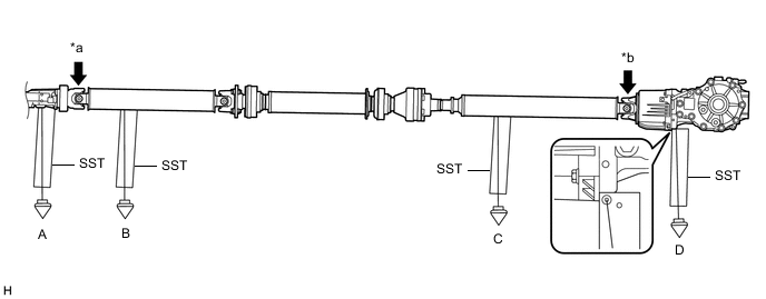
Using SST, measure the transfer assembly installation angle (A) and propeller shaft assembly installation angle (B).
- SST
- 09370-50010
No. 1 Joint Angle Measurement Position No. 1 Joint Angle A-B -3.34° to -1.34° (for 8AR-FTS)
-3.02° to -1.02° (for 2GR-FKS)
-
Using SST, measure the rear propeller shaft assembly installation angle (C) and rear differential carrier assembly installation angle (D).
- SST
- 09370-50010
No. 4 Joint Angle Measurement Position No. 4 Joint Angle C-D 0.85° to 2.85° If the measured angle is not within the specified range, adjust it with center No. 2 support bearing washers.
-
-
Adjust the No. 1 joint angle and No. 4 joint angle.
-
Select center No. 2 support bearing washers for adjustment.
Center No. 2 Support Bearing Washer Thickness Part No. Thickness mm (in.) 90201-10095 3.2 mm (0.126 in.) 90201-10081 4.5 mm (0.177 in.) 90201-10083 6.5 mm (0.256 in.) 90201-10084 9.0 mm (0.354 in.) 90201-10085 11.0 mm (0.433 in.) 90201-10086 13.5 mm (0.531 in.) 90201-10134 15.5 mm (0.610 in.) 90201-10135 17.5 mm (0.689 in.) Note
-
Make sure to use center No. 2 support bearing washers of the same thickness on both the right and left sides.
-
Do not use more than 1 adjusting washer per bolt.
-
-
-
-
INSTALL PROPELLER SHAFT GUARD (for Front Side)
-
Install the propeller shaft guard with the nut.
- Torque:
- 8.5 N*m { 87 kgf*cm, 75 in.*lbf }
-
-
INSTALL PROPELLER SHAFT GUARD (for Rear Side)
-
Install the propeller shaft guard with the 2 bolts.
- Torque:
- 32 N*m { 326 kgf*cm, 24 ft.*lbf }
-
-
INSTALL WIRING HARNESS CLAMP BRACKET
-
Install the wiring harness clamp bracket with the 2 bolts.
- Torque:
- 8.5 N*m { 87 kgf*cm, 75 in.*lbf }
-
Engage the 2 clamps.
-
-
INSTALL FRONT CENTER FLOOR COVER
for 8AR-FTS:
for 2GR-FKS (w/ Canister Pump Module):
for 2GR-FKS (w/o Canister Pump Module):
-
INSTALL FRONT FLOOR COVER LH
for 8AR-FTS:
for 2GR-FKS:
-
INSTALL NO. 2 ENGINE UNDER COVER
for 8AR-FTS:
for 2GR-FKS: