FRONT DRIVE SHAFT ASSEMBLY INSTALLATION

CAUTION / NOTICE / HINT
Tech Tips
-
Use the same procedure for the RH side and LH side.
-
The following procedure is for the LH side.
PROCEDURE
-
INSTALL FRONT DRIVE SHAFT HOLE SNAP RING (for LH Side)
-
Install a new front drive shaft hole snap ring.
Note
Face the end gap of the front drive shaft hole snap ring downward.
-
-
INSTALL FRONT DRIVE SHAFT ASSEMBLY LH
-
Coat the splines of the front drive inboard joint assembly with ATF WS.
-

Align the inboard joint splines, and using a brass bar and a hammer, install the front drive shaft assembly LH.
Note
-
Face the end gap of the front drive shaft hole snap ring downward.
-
Do not damage the front drive shaft oil seal LH.
-
Do not damage the front axle inboard joint boot.
-
Make sure to center the front drive shaft assembly LH during installation to prevent damage to the front drive shaft hole snap ring.
Tech Tips
Confirm whether the drive shaft is securely driven in by checking the reaction force and sound.
-
-


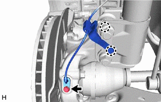
Toyota Body Grease W Apply 0.1 to 0.3 g (0.00353 to 0.0105 oz) of Toyota Body Grease W to each of the 4 areas shown in the illustration.
-

*a Matchmark Align the matchmarks and install the front drive shaft assembly LH to the front axle assembly.
Note
-
Do not damage the front disc brake dust cover.
-
Be careful not to damage the front axle outboard joint boot.
-
Check that there is no foreign matter on the contact surfaces.
-
Do not push the front axle assembly further out of the vehicle than is necessary.
-
-
-
INSTALL FRONT DRIVE SHAFT ASSEMBLY RH (for 2WD)
-
Install a new bearing bracket hole snap ring to the front drive shaft assembly RH.
-
Coat the splines of the front drive inboard joint assembly with ATF WS.
-
Align the inboard joint splines, and securely insert the front drive shaft assembly RH.
Note
-
Do not damage the front drive shaft oil seal RH.
-
Do not damage the front axle inboard joint boot.
-
When inserting the front drive shaft assembly RH, keep it level.
-
-

Install the bearing bracket hole snap ring and a new No. 1 drive shaft bearing bracket setting bolt.
- Torque:
- 32.4 N*m { 330 kgf*cm, 24 ft.*lbf }
-

Toyota Body Grease W Apply 0.1 to 0.3 g (0.00353 to 0.0105 oz) of Toyota Body Grease W to each of the 4 areas shown in the illustration.
-

*a Matchmark Align the matchmarks and install the front drive shaft assembly RH to the front axle assembly.
Note
-
Do not damage the front disc brake dust cover.
-
Be careful not to damage the front axle outboard joint boot.
-
Check that there is no foreign matter on the contact surfaces.
-
Do not push the front axle assembly further out of the vehicle than is necessary.
-
-
-
INSTALL FRONT DRIVE SHAFT ASSEMBLY RH (for AWD)
-
Install a new bearing bracket hole snap ring to the front drive shaft assembly RH.
-
Coat the splines of the front drive inboard joint assembly with Toyota genuine differential gearoil LT 75W-85 GL-5 or equivalent.
-
Align the inboard joint splines, and securely insert the front drive shaft assembly RH.
Note
-
Do not damage the transfer case oil seal RH.
-
Do not damage the front axle inboard joint boot.
-
When inserting the front drive shaft assembly RH, keep it level.
-
-

Install the bearing bracket hole snap ring and a new No. 1 drive shaft bearing bracket setting bolt.
- Torque:
- 32.4 N*m { 330 kgf*cm, 24 ft.*lbf }
-
Toyota Body Grease W Apply 0.1 to 0.3 g (0.00353 to 0.0105 oz) of Toyota Body Grease W to each of the 4 areas shown in the illustration.
-
*a Matchmark Align the matchmarks and install the front drive shaft assembly RH to the front axle hub sub-assembly.
Note
-
Do not damage the front disc brake dust cover.
-
Be careful not to damage the front axle outboard joint boot.
-
Check that there is no foreign matter on the contact surfaces.
-
Do not push the front axle assembly further out of the vehicle than is necessary.
-
-
-
CONNECT FRONT LOWER NO. 1 SUSPENSION ARM SUB-ASSEMBLY
-
INSTALL FRONT STABILIZER LINK ASSEMBLY
-
CONNECT TIE ROD ASSEMBLY
-
INSTALL FRONT SPEED SENSOR (w/o AVS)
-
Install the front speed sensor to the steering knuckle with the bolt.
- Torque:
- 8.5 N*m { 87 kgf*cm, 75 in.*lbf }
Note
-
Keep the tip of the front speed sensor and installation hole free of foreign matter.
-
Firmly insert the front speed sensor body into the steering knuckle before tightening the bolt.
-
After installing the front speed sensor to the steering knuckle, make sure that there is no clearance between the front speed sensor stay and steering knuckle. Also make sure that no foreign matter is stuck between the parts.
-
Do not twist the front speed sensor wire harness when installing it.
-
Engage the 2 claws to install the sensor clamp.
Note
Do not twist the front speed sensor wire harness when installing it.
-
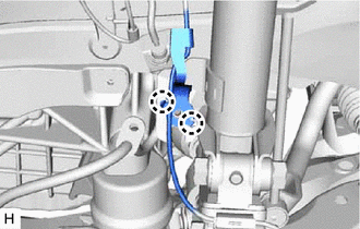
Engage the 2 claws to install the sensor clamp.
Note
Do not twist the front speed sensor wire harness when installing it.
-

Install the front flexible hose with the bolt.
- Torque:
- 18.8 N*m { 192 kgf*cm, 14 ft.*lbf }
-
-
INSTALL FRONT SPEED SENSOR (w/ AVS)
-

Install the front speed sensor to the steering knuckle with the bolt.
- Torque:
- 8.5 N*m { 87 kgf*cm, 75 in.*lbf }
Note
-
Keep the tip of the front speed sensor and installation hole free of foreign matter.
-
Firmly insert the front speed sensor body into the steering knuckle before tightening the bolt.
-
After installing the front speed sensor to the steering knuckle, make sure that there is no clearance between the front speed sensor stay and steering knuckle. Also make sure that no foreign matter is stuck between the parts.
-
Do not twist the front speed sensor wire harness when installing it.
-
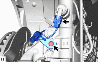
Install the front skid control sensor wire to the front shock absorber assembly with the bolt.
- Torque:
- 10 N*m { 102 kgf*cm, 7 ft.*lbf }
-
Connect the connector to the front shock absorber assembly.
Note
Do not twist the front skid control sensor wire harness when installing it.
-

Engage the 2 claws to install the sensor clamp.
Note
Do not twist the front skid control sensor wire harness when installing it.
-

Install the front flexible hose with the bolt.
- Torque:
- 18.8 N*m { 192 kgf*cm, 14 ft.*lbf }
-
-
INSTALL FRONT AXLE SHAFT NUT
-
Clean the threaded parts on the front drive shaft assembly and a new front axle shaft nut using non-residue solvent.
Note
-
Make sure to perform this work even when using a new front drive shaft assembly.
-
Keep the threaded parts free of oil and foreign matter.
-
-
Using a 30 mm deep socket wrench, install the front axle shaft nut.
- Torque:
- 294 N*m { 2998 kgf*cm, 217 ft.*lbf }
Tech Tips
Depress the brake pedal to prevent the drive shaft from rotating.
-

Using a chisel and hammer, stake the front axle shaft nut.
-
-
ADD TRANSFER OIL (for AWD)
-
ADD AUTOMATIC TRANSAXLE FLUID
for U661E:
for U661F:
for U881E:
for U881F:
-
INSPECT TRANSFER OIL LEAK (for AWD)
-
INSTALL FRONT FENDER APRON SEAL LH
for 8AR-FTS:
for 2GR-FKS:
-
INSTALL NO. 3 ENGINE UNDER COVER
for 8AR-FTS:
for 2GR-FKS:
-
INSTALL FRONT WHEEL OPENING EXTENSION PAD LH
for 8AR-FTS:
for 2GR-FKS:
-
INSTALL FRONT WHEELS
-
INSPECT AND ADJUST FRONT WHEEL ALIGNMENT
-
CHECK FOR SPEED SENSOR SIGNAL