PROPELLER SHAFT ASSEMBLY INSPECTION

PROCEDURE
-
INSPECT SPIDER BEARING
-
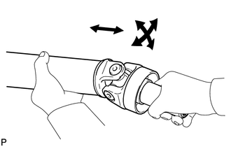
Check that the spider bearing rotates smoothly.
-
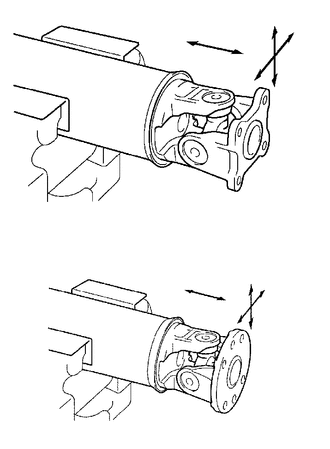
Check that there is no play in the spider bearing.
If necessary, replace the propeller with center bearing shaft assembly.
-
-
INSPECT INTERMEDIATE SHAFT ASSEMBLY
-
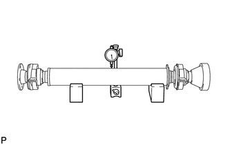
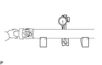
Using a dial indicator, measure the runout of the intermediate shaft assembly.
Maximum Runout 0.4 mm (0.0157 in.) Note
The dial indicator must be set at a right angle to the center of the intermediate shaft assembly.
If the shaft runout exceeds the maximum, replace the propeller with center bearing shaft assembly.
-
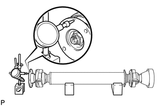
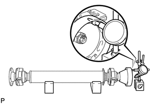
Using a dial indicator, measure the runout of the universal joint flange (for front side).
Maximum Runout 0.1 mm (0.00394 in.) If the shaft runout exceeds the maximum, replace the propeller with center bearing shaft assembly.
-
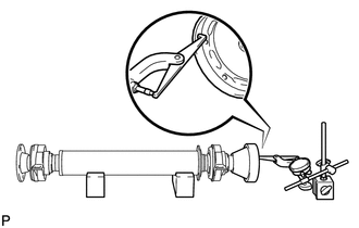
Using a dial indicator, measure the runout of the universal joint flange (for rear side).
Maximum Runout 0.1 mm (0.00394 in.) If the shaft runout exceeds the maximum, replace the propeller with center bearing shaft assembly.
-
Using a dial indicator, measure the runout of the universal joint flange (for rear side).
Maximum Runout 0.1 mm (0.00394 in.) If the shaft runout exceeds the maximum, replace the propeller with center bearing shaft assembly.
-
-
INSPECT PROPELLER SHAFT ASSEMBLY
-
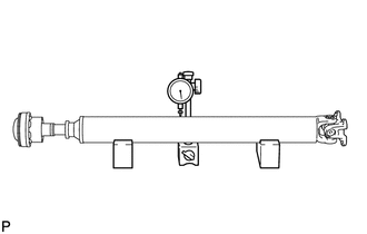
Using a dial indicator, measure the runout of the propeller shaft assembly.
Maximum Runout 0.4 mm (0.0157 in.) Note
The dial indicator must be set at a right angle to the center of the propeller shaft assembly.
If the shaft runout exceeds the maximum, replace the propeller with center bearing shaft assembly.
-
-
INSPECT REAR PROPELLER SHAFT ASSEMBLY
-
Using a dial indicator, measure the runout of the rear propeller shaft assembly.
Maximum Runout 0.4 mm (0.0157 in.) Note
The dial indicator must be set at a right angle to the center of the rear propeller shaft assembly.
If the shaft runout exceeds the maximum, replace the propeller with center bearing shaft assembly.
-
-
INSPECT CENTER NO. 2 SUPPORT BEARING ASSEMBLY
-
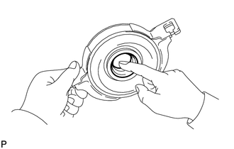
Turn the center No. 2 support bearing assembly by hand.
-
Check that the center No. 2 support bearing assembly turns smoothly, and check that the seals are not cracked or damaged.
If the center No. 2 support bearing assembly is damaged or worn, or does not turn smoothly, replace it.
-