TRANSFER ASSEMBLY REASSEMBLY

PROCEDURE
-
INSTALL REAR TRANSFER DRIVEN PINION BEARING (OUTER RACE)
-
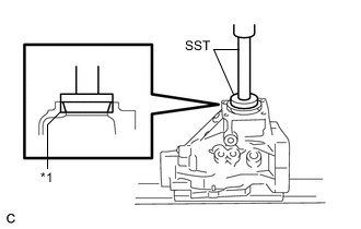
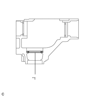
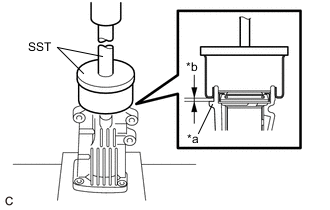
*1 Rear Transfer Driven Pinion Bearing (outer race) Using SST and a press, install the rear transfer driven pinion bearing (outer race) to the transfer case sub-assembly.
- SST
- 09950-60010 ( 09951-00620 )
- 09950-70010 ( 09951-07150 )
Note
-
Keep the transfer case sub-assembly horizontal using wooden blocks, etc.
-
If the rear transfer driven pinion bearing (outer race) is damaged or deformed, replace it with a new one.
-
Apply gear oil to the rear transfer driven pinion bearing (outer race).
-
-
INSTALL TRANSFER OUTPUT SHAFT WASHER
-
Apply gear oil to the transfer output shaft washer.
-
Install the transfer output shaft washer to the transfer case sub-assembly.
Note
If the transfer output shaft washer is damaged or deformed, replace it with a new one.
Tech Tips
Install the same transfer output shaft washer as the one removed.
-
-
INSTALL FRONT TRANSFER DRIVEN PINION BEARING
-
Apply gear oil to the inner surface of the transfer case sub-assembly.
-
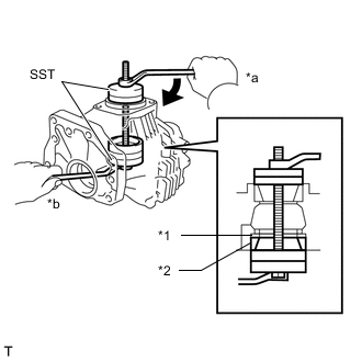
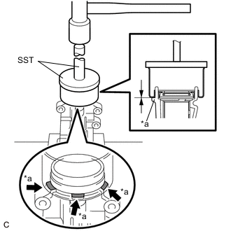
*1 Transfer Output Shaft Washer *2 Front Transfer Driven Pinion Bearing (outer race) *a Turn *b Hold Using SST, bolt and nut, install the front transfer driven pinion bearing (outer race) to the transfer case sub-assembly.
- SST
- 09950-60010 ( 09951-00610, 09951-00620, 09951-00650 )
- 09950-60020 ( 09951-00680 )
Note
-
If the front transfer driven pinion bearing (outer race) is damaged or deformed, replace it with a new one.
-
When replacing the front transfer driven pinion bearing (outer race), replace both outer and inner races as one set.
-
Apply gear oil to the front transfer driven pinion bearing (outer race).
-
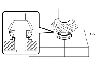
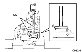
Using SST and a press, install the front transfer driven pinion bearing (inner race) to the driven pinion.
- SST
- 09506-30012
Note
-
If the front transfer driven pinion bearing (inner race) is damaged or deformed, replace it with a new one.
-
When replacing the front transfer driven pinion bearing (inner race), replace both outer and inner races as one set.
-
Apply gear oil to the front transfer driven pinion bearing (inner race).
-
-
INSTALL DRIVEN PINION
-
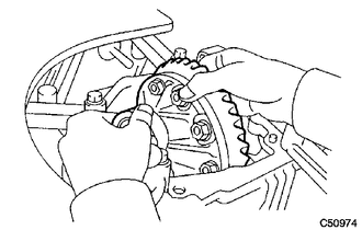
Install the driven pinion to the transfer case sub-assembly.
-
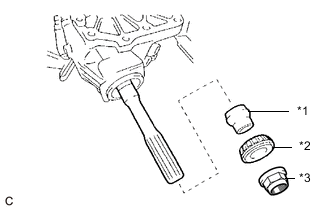
*1 Transfer Pinion Bearing Spacer *2 Rear Transfer Driven Pinion Bearing (inner race) *3 Gear Nut Apply gear oil to the rear transfer driven pinion bearing (inner race).
-
Install a new transfer pinion bearing spacer and the rear transfer driven pinion bearing (inner race) to the driven pinion.
Note
-
If the rear transfer driven pinion bearing (inner race) is damaged or deformed, replace it with a new one.
-
When replacing the rear transfer driven pinion bearing (inner race), replace both outer and inner races as one set.
Tech Tips
Install the transfer pinion bearing spacer with the larger inner diameter facing forward as shown in the illustration.
-
-
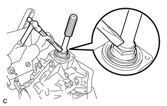
Apply hypoid gear oil LSD to the threads of a new gear nut and its seating surface.
-
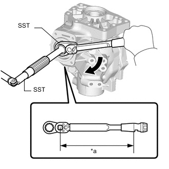
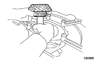
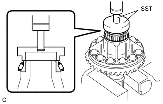
*a Torque Wrench Fulcrum Length Using SST, install the gear nut.
- SST
- 09326-20011
- 09556-16030
Torque Specified tightening torque 270 to 420 N*m (2753 to 4283 kgf*cm, 199 to 310 ft.*lbf) Note
-
This torque value is effective when SST is parallel to the torque wrench.
-
Do not stake the gear nut until the final preload, tooth contact and backlash adjustments are completed.
Tech Tips
-
Calculate the torque wrench reading when changing the fulcrum length of the torque wrench.
-
When using SST (fulcrum length of 50 mm (1.97 in.)) + torque wrench (fulcrum length of 1100 mm (3.61 ft.)):
258 to 402 N*m (2631 to 4099 kgf*cm, 190 to 296 ft.*lbf)
-
-
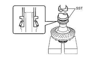
ADJUST DRIVEN PINION PRELOAD
-
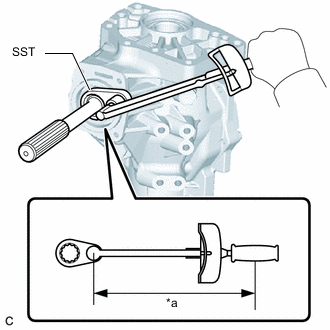
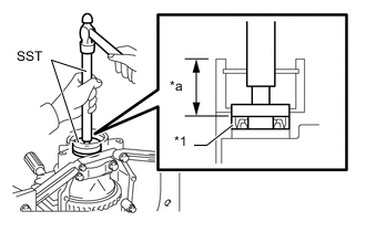
*a Torque Wrench Fulcrum Length Using SST and a torque wrench, measure the driven pinion preload.
- SST
- 09326-20011
Specified Preload (at Starting) Item Preload New bearing 0.7 to 1.4 N*m (7 to 14 kgf*cm, 6 to 12 in.*lbf) Reused bearing 0.5 to 0.9 N*m (5 to 9 kgf*cm, 4 to 8 in.*lbf) Note
Turn the driven pinion counterclockwise and clockwise several times.
Tech Tips
-
Calculate the torque wrench reading when changing the fulcrum length of the torque wrench.
-
When using SST (fulcrum length of 50 mm (1.97 in.)) + torque wrench (fulcrum length of 130 mm (5.12 in.)):
Preload (at Starting) Item Preload New bearing 0.5 to 1.0 N*m (5 to 10 kgf*cm, 4 to 9 in.*lbf) Reused bearing 0.3 to 0.6 N*m (3 to 6 kgf*cm, 3 to 5 in.*lbf)
-
If the preload is more than the specification, replace the transfer pinion bearing spacer with a new one.
-
If the preload is not sufficient, adjust the driven pinion by tightening the gear nut 5° to 10° and measuring the preload until the preload is within the specification.
-
Even if the tightening torque of the gear nut exceeds the specified torque, if the preload is insufficient, loosen the gear nut once and apply rust preventive oil or hypoid gear oil LSD to the gear nut and to the screw or rear transfer driven pinion bearing (inner race) surface of the driven pinion. Then perform the procedure again. If the tightening torque is less than the specified torque, replace the transfer pinion bearing spacer with a new one and adjust it.
Note
Do not loosen the gear nut to reduce the preload.
-
-
INSTALL RING GEAR
-
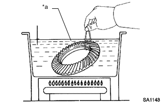
*a Boiling Water Heat the ring gear in boiling water.
-
Secure the transfer ring gear mounting case in a vise using aluminum plates.
Note
-
Be careful not to damage the transfer ring gear mounting case in the vise.
-
Remove any oil and water from the ring gear contact surface of the transfer ring gear mounting case.
-
Clean the bolt holes in the transfer ring gear mounting case.
-
-
Carefully remove the ring gear from the boiling water.
CAUTION:
Make sure to wear protective gloves as the ring gear is extremely hot.
-
*a Matchmark After the moisture on the ring gear has completely evaporated, quickly align the matchmarks and set the ring gear to the transfer ring gear mounting case.
Note
There is no foreign matter on the contact surfaces of the transfer ring gear mounting case and ring gear.
-
Apply adhesive to the bolt holes and contact surface of the 12 bolts.
Adhesive Toyota Genuine Adhesive 1324, Three Bond 1324 or equivalent Note
-
Apply adhesive after the ring gear has cooled down sufficiently.
-
Make sure to install the bolts immediately after applying adhesive to keep foreign matter away from them.
-
-
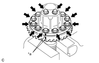
Install the ring gear with the 12 bolts.
- Torque:
- 98.6 N*m { 1005 kgf*cm, 73 ft.*lbf }
Note
-
Tighten the bolts evenly in a diagonal pattern using several steps.
-
Tighten the bolts after the ring gear has cooled down sufficiently.
-
-
INSTALL RING GEAR MOUNTING CASE BEARING
-
for LH side:
-
Using SST and a press, install the ring gear mounting case bearing (inner race) to the transfer ring gear mounting case.
- SST
- 09223-00010
- 09726-40010
Note
-
If the ring gear mounting case bearing (inner race) is damaged or deformed, replace it with a new one.
-
When replacing the ring gear mounting case bearing (inner race), replace both outer and inner races as one set.
-
Install the ring gear mounting case plate washer to the transfer case sub-assembly.
Note
If the ring gear mounting case plate washer is damaged or deformed, replace it with a new one.
Tech Tips
Use a new ring gear mounting case plate washer with the same thickness as the one removed when installing the ring gear mounting case bearing (outer race).
-
Using SST and a press, install the ring gear mounting case bearing (outer race) to the transfer case sub-assembly.
- SST
- 09950-60010 ( 09951-00680 )
- 09950-70010 ( 09951-07200 )
Note
-
If the ring gear mounting case bearing (outer race) is damaged or deformed, replace it with a new one.
-
When replacing the ring gear mounting case bearing (outer race), replace both outer and inner races as one set.
-
Apply gear oil to the ring gear mounting case bearing.
-
-
for RH side:
-
Using SST and a press, install the ring gear mounting case bearing (inner race) to the transfer ring gear mounting case.
- SST
- 09387-00010
- 09950-70010 ( 09951-07100 )
Note
-
If the ring gear mounting case bearing (inner race) is damaged or deformed, replace it with a new one.
-
When replacing the ring gear mounting case bearing (inner race), replace both outer and inner races as one set.
-
Install the ring gear mounting case bearing (outer race) to the transfer ring gear mounting case.
Note
-
If the ring gear mounting case bearing (outer race) is damaged or deformed, replace it with a new one.
-
When replacing the ring gear mounting case bearing (outer race), replace both outer and inner races as one set.
-
-
Apply gear oil to the ring gear mounting case bearing.
-
-
-
INSTALL TRANSFER RING GEAR MOUNTING CASE
-
Install the transfer ring gear mounting case to the transfer case sub-assembly.
-
-
INSTALL NO. 1 TRANSFER OUTPUT SHAFT SPACER
-
Apply gear oil to the No. 1 transfer output shaft spacer.
-
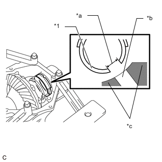
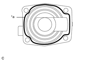
*1 No. 1 Transfer Output Shaft Spacer *a Cutout *b Transfer Case Hole *c Transfer Case Sub-assembly Align the cutout on the No. 1 transfer output shaft spacer with the transfer case hole to install it as shown in the illustration.
-
-
INSTALL NO. 2 TRANSFER RING GEAR MOUNTING CASE WASHER
-
Apply gear oil to the No. 2 transfer ring gear mounting case washer.
-
Using a brass bar and a hammer, install the No. 2 transfer ring gear mounting case washer to the transfer case sub-assembly.
Tech Tips
Use a No. 2 transfer ring gear mounting case washer with the same thickness as the one removed.
-
-
INSTALL BEARING CAP
-
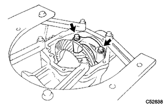
Install the bearing cap to the transfer case sub-assembly with the 2 bolts.
- Torque:
- 63.2 N*m { 644 kgf*cm, 47 ft.*lbf }
-
-
INSPECT RING GEAR BACKLASH
-
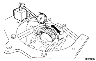
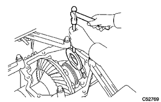
Set a dial indicator perpendicular to a ring gear tooth tip.
-
Secure the driven pinion in place and move the ring gear back and forth to measure the backlash.
Backlash 0.14 to 0.25 mm (0.00551 to 0.00984 in.) Note
Check at least 3 positions on the circumference of the ring gear.
-
*1 Ring Gear Mounting Case Plate Washer If the backlash is outside the specified range, select a ring gear mounting case plate washer from the table below and install it to meet the specified range.
Tech Tips
If the backlash is more than specified, select a thinner ring gear mounting case plate washer. If the backlash is less than specified, select a thicker ring gear mounting case plate washer.
Ring Gear Mounting Case Plate Washer Thickness Part Number Thickness
(mm (in.))
Mark 36265-48J60 1.95
(0.0768)
5Q 36265-48J70 1.97
(0.0776)
5R 36265-48J80 1.99
(0.0783)
5S 36265-48J90 2.01
(0.0791)
5T 36265-48K00 2.03
(0.0799)
5U 36265-48K10 2.05
(0.0807)
5V 36265-48K20 2.07
(0.0815)
5W 36265-48K30 2.09
(0.0823)
5X 36265-48K40 2.11
(0.0831)
5Y 36265-48K50 2.13
(0.0839)
5Z 36265-48K60 2.15
(0.0846)
6F 36265-48K70 2.17
(0.0854)
6G 36265-48K80 2.19
(0.0862)
6H 36265-48K90 2.21
(0.0870)
6J 36265-48L00 2.23
(0.0878)
6K 36265-48L10 2.25
(0.0886)
6L 36265-48L20 2.27
(0.0894)
6M 36265-48L30 2.29
(0.0902)
6N 36265-48L40 2.31
(0.0909)
6P 36265-48L50 2.33
(0.0917)
6Q 36265-48L60 2.35
(0.0925)
6R 36265-48L70 2.37
(0.0933)
6S 36265-48L80 2.39
(0.0941)
6T 36265-48L90 2.41
(0.0949)
6U 36265-48M00 2.43
(0.0957)
6V 36265-48M10 2.45
(0.0965)
6W 36265-48M20 2.47
(0.0972)
6X 36265-48M30 2.49
(0.0980)
6Y 36265-48M40 2.51
(0.0988)
6Z 36265-48M50 2.53
(0.0996)
7F 36265-48M60 2.55
(0.100)
7G 36265-48M70 2.57
(0.101)
7H 36265-48M80 2.59
(0.102)
7J 36265-48M90 2.61
(0.103)
7K 36265-48N00 2.63
(0.10354)
7L 36265-48N10 2.65
(0.10433)
7M 36265-48N20 2.67
(0.105)
7N 36265-48N30 2.69
(0.106)
7P 36265-48N40 2.71
(0.10669)
7Q 36265-48N50 2.73
(0.10748)
7R 36265-48N60 2.75
(0.108)
7S 36265-48N70 2.77
(0.109)
7T 36265-48N80 2.79
(0.110)
7U 36265-48N90 2.81
(0.11063)
7V 36265-48P00 2.83
(0.11142)
7W 36265-48P10 2.85
(0.112)
7X 36265-48P20 2.87
(0.113)
7Y 36265-48P30 2.89
(0.114)
7Z 36265-48P40 2.91
(0.11457)
8F 36265-48P50 2.93
(0.11535)
8G 36265-48P60 2.95
(0.116)
8H 36265-48P70 2.97
(0.117)
8J 36265-48P80 2.99
(0.118)
8K 36265-48P90 3.01
(0.11850)
8L 36265-48Q00 3.03
(0.11929)
8M 36265-48Q10 3.05
(0.120)
8N 36265-48Q20 3.07
(0.121)
8P 36265-48Q30 3.09
(0.12165)
8Q 36265-48Q40 3.11
(0.12244)
8R 36265-48Q50 3.13
(0.123)
8S 36265-48Q60 3.15
(0.124)
8T 36265-48Q70 3.17
(0.125)
8U 36265-48Q80 3.19
(0.12559)
8V 36265-48Q90 3.21
(0.12638)
8W 36265-48R00 3.23
(0.127)
8X 36265-48R10 3.25
(0.128)
8Y 36265-48R20 3.27
(0.129)
8Z 36265-48R30 3.29
(0.12953)
9D 36265-48R40 3.31
(0.13031)
9E 36265-48R50 3.33
(0.131)
9F 36265-48R60 3.35
(0.132)
9G 36265-48R70 3.37
(0.133)
9H
-
-
INSPECT TOOTH CONTACT BETWEEN RING GEAR AND DRIVEN PINION
-
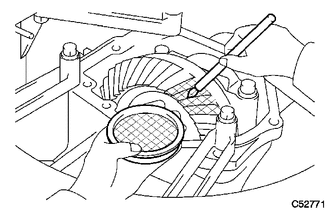
Apply a light coat of Prussian blue evenly to both sides of all teeth.
-
Rotate the ring gear 10 times or more.
-
Rotate the ring gear to inspect the tooth contact pattern.
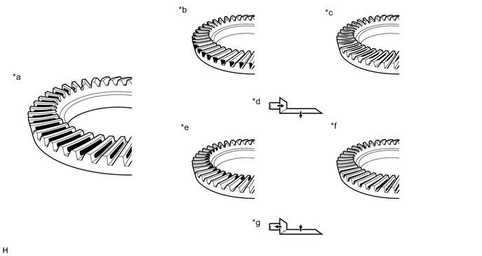
*a Proper Contact *b Heel Contact *c Face Contact *d Select an adjusting washer that will shift the driven pinion closer to the ring gear (*b, *c) *e Toe Contact *f Flank Contact *g Select an adjusting washer that will shift the driven pinion away from the ring gear (*e, *f) - - Note
Check at least 4 positions on the circumference of the ring gear.
Tech Tips
Prussian blue shown in the illustration indicates the tooth contact pattern.
-
*1 Transfer Output Shaft Washer If the tooth contact pattern is not correct, select a new transfer output shaft washer that is thicker or thinner as necessary and recheck.
Transfer Output Shaft Washer Thickness Part Number Thickness
(mm (in.))
Mark 36275-48010 2.00
(0.0787)
ZA 36275-48020 2.02
(0.0795)
ZB 36275-48030 2.04
(0.0803)
ZC 36275-48040 2.06
(0.0811)
ZD 36275-48050 2.08
(0.0819)
ZE 36275-33010 2.10
(0.0827)
AA 36275-33030 2.12
(0.0835)
AC 36275-33050 2.14
(0.0843)
BB 36275-33070 2.16
(0.0850)
CA 36275-33090 2.18
(0.0858)
CC 36275-33110 2.20
(0.0866)
DB 36275-33130 2.22
(0.0874)
EA 36275-33150 2.24
(0.0882)
EC 36275-33170 2.26
(0.0890)
FB 36275-33190 2.28
(0.0898)
GA 36275-33210 2.30
(0.0906)
GC 36275-33230 2.32
(0.0913)
HB 36275-33250 2.34
(0.0921)
JA 36275-33270 2.36
(0.0929)
JC 36275-33290 2.38
(0.0937)
KB 36275-33310 2.40
(0.0945)
LA 36275-33330 2.42
(0.0953)
LC 36275-33350 2.44
(0.0961)
MB 36275-33370 2.46
(0.0969)
NA 36275-33390 2.48
(0.0976)
NC 36275-33410 2.50
(0.0984)
PB 36275-33430 2.52
(0.0992)
QA 36275-33450 2.54
(0.100)
QC 36275-48060 2.56
(0.101)
RA 36275-48070 2.58
(0.10157)
RB 36275-48080 2.60
(0.10236)
RC 36275-48090 2.62
(0.103)
SA 36275-48100 2.64
(0.104)
SB 36275-48110 2.66
(0.105)
SC 36275-48120 2.68
(0.10551)
TA 36275-48130 2.70
(0.10630)
TB 36275-48140 2.72
(0.107)
TC
-
-
INSPECT AND ADJUST TOTAL PRELOAD
-
*a Torque Wrench Fulcrum Length 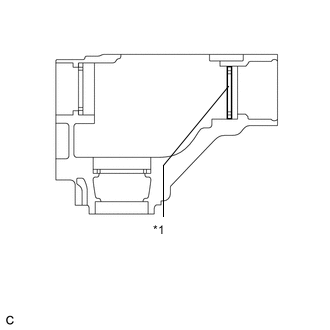
*1 No. 2 Transfer Ring Gear Mounting Case Washer Using SST and a torque wrench, measure the total preload.
- SST
- 09326-20011
Specified Total Preload (at Starting) Item Preload New bearing 0.5 to 0.7 N*m (5 to 7 kgf*cm, 4 to 6 in.*lbf) + Driven pinion preload Reused bearing 0.4 to 0.5 N*m (4.1 to 5.1 kgf*cm, 3.5 to 4.4 in.*lbf) + Driven pinion preload Note
Turn the driven pinion counterclockwise and clockwise several times.
Tech Tips
-
Calculate the torque wrench reading when changing the fulcrum length of the torque wrench.
-
When using SST (fulcrum length of 50 mm (1.97 in.)) + torque wrench (fulcrum length of 130 mm (5.12 in.)):
Total Preload (at Starting) Item Preload New bearing 0.4 to 0.5 N*m (4.1 to 5.1 kgf*cm, 3.5 to 4.4 in.*lbf) + Driven pinion preload Reused bearing 0.25 to 0.38 N*m (3 to 4 kgf*cm, 2 to 3 in.*lbf) + Driven pinion preload
If the preload is outside the specified range, replace the No. 2 transfer ring gear mounting case washer with one that is thicker or thinner as necessary and recheck.
No. 2 Transfer Ring Gear Mounting Case Washer Thickness Part Number Thickness
(mm (in.))
Mark 36266-48220 2.47
(0.0972)
G7 36266-48230 2.49
(0.0980)
G8 36266-48240 2.51
(0.0988)
G9 36266-48250 2.53
(0.0996)
H0 36266-48260 2.55
(0.100)
H1 36266-48270 2.57
(0.101)
H2 36266-48280 2.59
(0.102)
H3 36266-48290 2.61
(0.103)
H4 36266-48300 2.63
(0.10354)
H5 36266-48310 2.65
(0.10433)
H6 36266-48320 2.67
(0.105)
H7 36266-48330 2.69
(0.106)
H8 36266-48340 2.71
(0.10669)
H9 36266-48350 2.73
(0.10748)
J0 36266-48360 2.75
(0.108)
J1 36266-48370 2.77
(0.109)
J2 36266-48380 2.79
(0.110)
J3 36266-48390 2.81
(0.11063)
J4 36266-48400 2.83
(0.11142)
J5 36266-48410 2.85
(0.112)
J6 36266-48420 2.87
(0.113)
J7 36266-48430 2.89
(0.114)
J8 36266-48440 2.91
(0.11457)
J9 36266-48450 2.93
(0.11535)
K0 36266-48460 2.95
(0.116)
K1 36266-48470 2.97
(0.117)
K2 36266-48480 2.99
(0.118)
K3 36266-48490 3.01
(0.11850)
K4 36266-48500 3.03
(0.11929)
K5 36266-48510 3.05
(0.120)
K6 36266-48520 3.07
(0.121)
K7 36266-48530 3.09
(0.12165)
K8 36266-48540 3.11
(0.12244)
K9 36266-48550 3.13
(0.123)
L0 36266-48560 3.15
(0.124)
L1 36266-48570 3.17
(0.125)
L2 36266-48580 3.19
(0.12559)
L3 36266-48590 3.21
(0.12638)
L4 36266-48600 3.23
(0.127)
L5 36266-48610 3.25
(0.128)
L6 36266-48620 3.27
(0.129)
L7 36266-48630 3.29
(0.12953)
L8 36266-48640 3.31
(0.13031)
L9 36266-48650 3.33
(0.131)
M0 36266-48660 3.35
(0.132)
M1 36266-48670 3.37
(0.13268)
M2 36266-48680 3.39
(0.13346)
M3 36266-48690 3.41
(0.134)
M4 36266-48700 3.43
(0.135)
M5 36266-48710 3.45
(0.136)
M6 36266-48720 3.47
(0.13661)
M7 36266-48730 3.49
(0.13740)
M8 36266-48740 3.51
(0.138)
M9 36266-48750 3.53
(0.139)
N0 36266-48760 3.55
(0.13976)
N1 36266-48770 3.57
(0.14055)
N2 36266-48780 3.59
(0.14134)
N3 36266-48790 3.61
(0.142)
N4 36266-48800 3.63
(0.143)
N5 36266-48810 3.65
(0.14370)
N6 36266-48820 3.67
(0.14449)
N7 36266-48830 3.69
(0.145)
N8 36266-48840 3.71
(0.146)
N9 36266-48850 3.73
(0.147)
P0 36266-48860 3.75
(0.14764)
P1 36266-48870 3.77
(0.14842)
P2 36266-48880 3.79
(0.149)
P3 36266-48890 3.81
(0.150)
P4 36266-48A00 3.83
(0.151)
P5 36266-48A10 3.85
(0.15157)
P6 36266-48A20 3.87
(0.15236)
P7 36266-48A30 3.89
(0.153)
P8 36266-48A40 3.91
(0.154)
P9 36266-48A50 3.93
(0.155)
Q0 36266-48A60 3.95
(0.15551)
Q1 36266-48A70 3.97
(0.15630)
Q2 36266-48A80 3.99
(0.157)
Q3 36266-48A90 4.01
(0.158)
Q4 36266-48B00 4.03
(0.15866)
Q5 36266-48B10 4.05
(0.15945)
Q6 36266-48B20 4.07
(0.160)
Q7 36266-48B30 4.09
(0.161)
Q8 36266-48B40 4.11
(0.162)
Q9 36266-48B50 4.13
(0.16260)
R0 36266-48B60 4.15
(0.16339)
R1 36266-48B70 4.17
(0.164)
R2 36266-48B80 4.19
(0.165)
R3 36266-48B90 4.21
(0.166)
R4 36266-48C00 4.23
(0.16654)
R5 36266-48C10 4.25
(0.16732)
R6 36266-48C20 4.27
(0.168)
R7 36266-48C30 4.29
(0.169)
R8 36266-48C40 4.31
(0.16968)
R9 36266-48C50 4.33
(0.17047)
S0 36266-48C60 4.35
(0.171)
S1 36266-48C70 4.37
(0.172)
S2 36266-48C80 4.39
(0.173)
S3 36266-48C90 4.41
(0.17362)
S4 36266-48D00 4.43
(0.17441)
S5 36266-48D10 4.45
(0.175)
S6 -
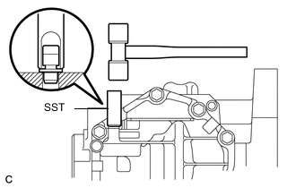
Using a chisel and a hammer, stake the gear nut.
-
-
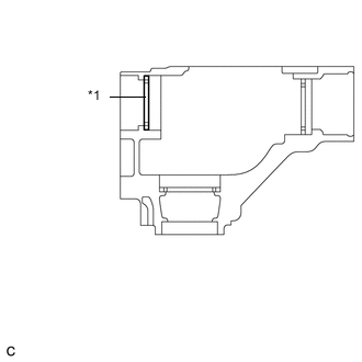
INSTALL TRANSFER CASE OIL SEAL RH
-
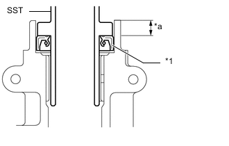
*1 Transfer Case Oil Seal RH *a Depth Using SST and a hammer, install a new transfer case oil seal RH to the transfer case sub-assembly until it reaches the position shown in the illustration.
- SST
- 09950-60010 ( 09951-00340, 09951-00580, 09952-06010 )
- 09950-70010 ( 09951-07150 )
Standard Depth 33.5 to 34.5 mm (1.32 to 1.36 in.) Note
-
Make sure that the transfer case oil seal RH is not tilted.
-
Do not tap in the transfer case oil seal RH in too far.
-
Coat the lip of the transfer case oil seal RH with MP grease.
-
-
INSTALL TRANSFER CASE OIL SEAL
-

*1 Transfer Case Oil Seal *a Depth Using SST and a hammer, install a new transfer case oil seal to the transfer case sub-assembly until it reaches the position shown in the illustration.
- SST
- 09608-10010
- 09950-70010 ( 09951-07150 )
Standard Depth 9.5 to 10.5 mm (0.374 to 0.413 in.) Note
-
Make sure that the transfer case oil seal is not tilted.
-
Do not tap in the transfer case oil seal in too far.
-
Coat the lip of the transfer case oil seal with MP grease.
-
-
INSTALL TRANSFER EXTENSION HOUSING TYPE T OIL SEAL
-
*1 Transfer Extension Housing Type T Oil Seal *a Depth Using SST and a hammer, install a new transfer extension housing type T oil seal to the transfer extension housing sub-assembly until it reaches the position shown in the illustration.
- SST
- 09325-20010
Standard Depth 9.8 to 10.6 mm (0.386 to 0.417 in.) Note
-
Make sure that the transfer extension housing type T oil seal is not tilted.
-
Do not tap in the transfer extension housing type T oil seal in too far.
-
Coat the lip of the transfer extension housing type T oil seal with MP grease.
-
-
INSTALL TRANSFER EXTENSION HOUSING DUST DEFLECTOR
-
*a Rib *b Approximately 1 to 2 mm (0.0394 to 0.0787 in.) Using SST and a press, install a new transfer extension housing dust deflector to the transfer extension housing sub-assembly so that the clearance between the rib of the transfer extension housing sub-assembly and the transfer extension housing dust deflector is approximately 1 to 2 mm (0.0394 to 0.0787 in.).
- SST
- 09950-60020 ( 09951-01030 )
- 09950-70010 ( 09951-07150 )
-
*a Rib Using SST and a hammer, tap in the transfer extension housing dust deflector until it contacts the rib of the transfer extension housing sub-assembly.
- SST
- 09950-60020 ( 09951-01030 )
- 09950-70010 ( 09951-07150 )
Note
Make sure that the transfer extension housing dust deflector evenly contacts the 3 ribs of the transfer extension housing sub-assembly.
-
-
INSTALL TRANSFER EXTENSION HOUSING SUB-ASSEMBLY
-
Remove any FIPG and be careful not to drop oil on the contact surfaces of the transfer extension housing sub-assembly and transfer case sub-assembly.
-
Degrease the surfaces with a non-residue solvent.
-
*a FIPG Apply FIPG to the transfer extension housing sub-assembly.
FIPG Toyota Genuine Seal Packing 1281, Three Bond 1281 or equivalent Note
-
Apply FIPG in a continuous line (width 1.2 mm (0.0472 in.)) along the sealing surface of the transfer extension housing sub-assembly.
-
Assemble the transfer extension housing sub-assembly within 10 minutes of FIPG application.
-
-
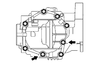
Install the transfer extension housing sub-assembly to the transfer case sub-assembly with the 4 bolts.
- Torque:
- 25.5 N*m { 260 kgf*cm, 19 ft.*lbf }
-
-
REMOVE TRANSFER ASSEMBLY
-
Remove the transfer assembly from the overhaul attachment.
-
-
INSTALL TRANSFER CASE STRAIGHT PIN
-
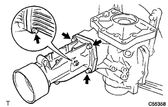
Using a plastic hammer, install the 4 transfer case straight pins to the transfer case sub-assembly at the positions shown in the illustration.
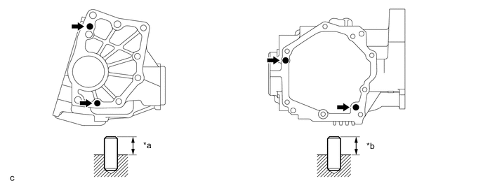
*a 10.8 to 11.8 mm (0.425 to 0.465 in.) *b 5.7 to 6.7 mm (0.224 to 0.264 in.)
-
-
INSTALL BREATHER OIL DEFLECTOR
-
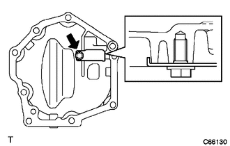
Install the breather oil deflector to the transfer case cover sub-assembly with the bolt.
- Torque:
- 6.5 N*m { 66 kgf*cm, 58 in.*lbf }
Note
Make sure that the breather oil deflector is installed in the correct direction.
-
-
INSTALL TRANSFER CASE COVER SUB-ASSEMBLY
-
Remove any FIPG and be careful not to drop oil on the contact surfaces of the transfer case cover sub-assembly and transfer case sub-assembly.
-
Degrease the surfaces with a non-residue solvent.
-
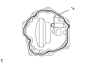
*a FIPG Apply FIPG to the transfer case cover sub-assembly.
FIPG Toyota Genuine Seal Packing 1281, Three Bond 1281 or equivalent Note
-
Apply FIPG in a continuous line (width 1.2 mm (0.0472 in.)) along the sealing surface of the transfer case cover sub-assembly.
-
Assemble the transfer case cover sub-assembly within 10 minutes after the FIPG application.
-
-
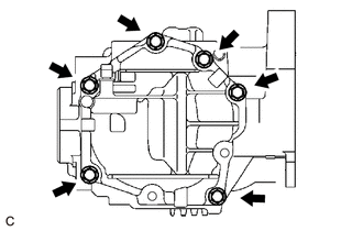
Install the transfer case cover sub-assembly to the transfer case sub-assembly with the 6 bolts.
- Torque:
- 19.6 N*m { 200 kgf*cm, 14 ft.*lbf }
-
Install 2 new bolts.
- Torque:
- 19.6 N*m { 200 kgf*cm, 14 ft.*lbf }
Note
Wait for at least 1 hour after installing the transfer case cover sub-assembly before adding transfer oil.
-
-
INSTALL TRANSFER CASE BREATHER PLUG
-
Using SST and a hammer, install a new transfer case breather plug to the transfer case cover sub-assembly.
- SST
- 09612-10093 ( 09612-10061 )
-
-
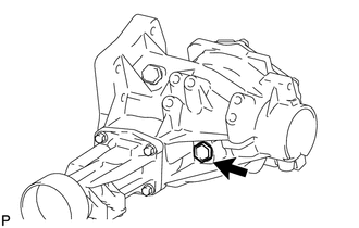
INSTALL TRANSFER DRAIN PLUG
-
Install a new gasket to the transfer drain plug.
-
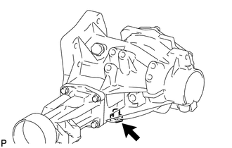
Install the transfer drain plug to the transfer case sub-assembly.
- Torque:
- 49 N*m { 500 kgf*cm, 36 ft.*lbf }
-
-
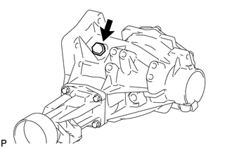
INSTALL FILLER PLUG (NO. 1 TRANSFER CASE PLUG)
-
Install a new gasket to the filler plug (No. 1 transfer case plug).
-
Install the filler plug (No. 1 transfer case plug) to the transfer case sub-assembly.
- Torque:
- 49 N*m { 500 kgf*cm, 36 ft.*lbf }
-
-
INSTALL NO. 2 TRANSFER CASE PLUG
-
Install a new gasket to the No. 2 transfer case plug.
-
Install the No. 2 transfer case plug to the transfer case sub-assembly.
- Torque:
- 49 N*m { 500 kgf*cm, 36 ft.*lbf }
-
-
INSTALL TRANSFER AND TRANSAXLE SETTING STUD BOLT
-
Install 4 new transfer and transaxle setting stud bolts to the transfer case sub-assembly at the positions shown in the illustration.
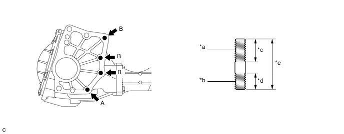
*a Automatic Transaxle Assembly Side *b Transfer Case Sub-assembly Side *c 30 mm (1.18 in.) *d 22 mm (0.866 in.) *e 64 mm (2.52 in.) - - - Torque:
- Transfer and Transaxle Setting Stud Bolt (A)
- 39.2 N*m { 400 kgf*cm, 29 ft.*lbf }
- Transfer and Transaxle Setting Stud Bolt (B)
- 25 N*m { 255 kgf*cm, 18 ft.*lbf }
Note
Install the sealed side of the transfer and transaxle setting stud bolt to the transfer case sub-assembly.
-