DYNAMIC TORQUE CONTROL AWD SYSTEM, Diagnostic DTC:C1298/98

| DTC Code | DTC Name |
|---|---|
| C1298/98 | Linear Solenoid Circuit |
DESCRIPTION
The 4WD ECU assembly receives signals from each sensor. The signals are used to control the clutch fluid pressure to vary the distribution of torque in accordance with the driving conditions.
| DTC No. | Detection Item | DTC Detection Condition | Trouble Area |
|---|---|---|---|
| C1298/98 | Linear Solenoid Circuit | When all of the following continue for 1 second or more:
|
|
WIRING DIAGRAM
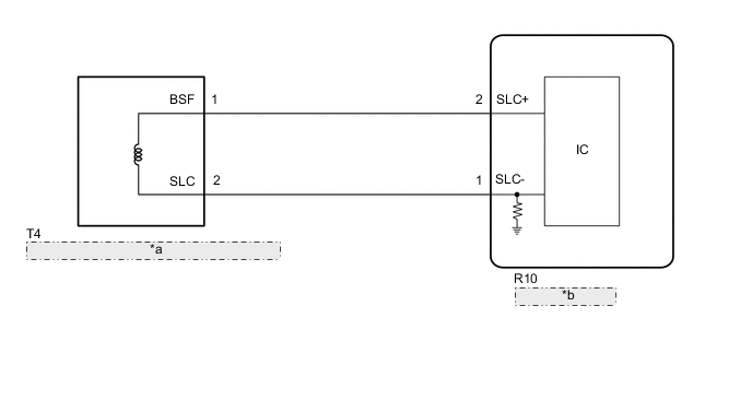
| *a | 4WD Linear Solenoid (Electro Magnetic Control Coupling Sub-assembly) |
| *b | 4WD ECU Assembly |
CAUTION / NOTICE / HINT
Note
When the 4WD ECU assembly is replaced with a known good one from another vehicle, it is necessary to perform calibration.
PROCEDURE
-
CHECK HARNESS AND CONNECTOR (4WD ECU ASSEMBLY - ELECTRO MAGNETIC CONTROL COUPLING SUB-ASSEMBLY)
-
Disconnect the R10 4WD ECU assembly connector.
-
Measure the resistance according to the value(s) in the table below.
Standard Resistance Tester Connection Condition Specified Condition R10-2 (SLC+) - R10-1 (SLC-) 20°C (68°F) 1.75 to 2.15 Ω R10-2 (SLC+) - Body ground Always 10 kΩ or higher R10-1 (SLC-) - Body ground Always 10 kΩ or higher Result Proceed to OK NG
OK 
REPLACE 4WD ECU ASSEMBLY Click here
NG 
-
-
INSPECT ELECTRO MAGNETIC CONTROL COUPLING SUB-ASSEMBLY
-
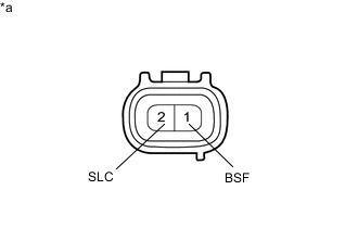
*a Component without harness connected
(4WD Linear Solenoid (Electro Magnetic Control Coupling Sub-assembly))
Disconnect the T4 4WD linear solenoid (electro magnetic control coupling sub-assembly) connector.
-
Measure the resistance according to the value(s) in the table below.
Standard Resistance Tester Connection Condition Specified Condition 1 (BSF) - 2 (SLC) 20°C (68°F) 1.75 to 2.15 Ω 1 (BSF) - Body ground Always 10 kΩ or higher 2 (SLC) - Body ground Always 10 kΩ or higher Result Proceed to OK NG
OK
REPAIR OR REPLACE HARNESS OR CONNECTOR
NG
REPLACE ELECTRO MAGNETIC CONTROL COUPLING SUB-ASSEMBLY Click here
-