DYNAMIC TORQUE CONTROL AWD SYSTEM, Diagnostic DTC:C1241/94

| DTC Code | DTC Name |
|---|---|
| C1241/94 | Low Power Supply Voltage |
DESCRIPTION
If a malfunction in the power source circuit occurs, or a communication malfunction with the skid control ECU (brake actuator assembly) or speed sensor occurs, the 4WD ECU assembly prohibits operation.
| DTC No. | Detection Item | DTC Detection Condition | Trouble Area |
|---|---|---|---|
| C1241/94 | Low Power Supply Voltage |
|
|
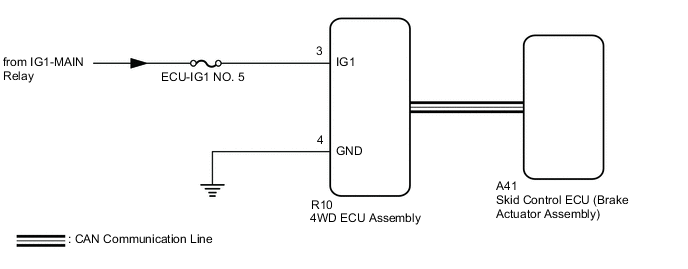
WIRING DIAGRAM
CAUTION / NOTICE / HINT
Note
-
Inspect the fuses for circuits related to this system before performing the following inspection procedure.
-
When the 4WD ECU assembly is replaced with a known good one from another vehicle, it is necessary to perform calibration.
PROCEDURE
-
CHECK FOR DTC (CAN COMMUNICATION SYSTEM AND VEHICLE STABILITY CONTROL SYSTEM)
-
Check if CAN communication DTCs are output.
-
Start the engine.
-
Drive the vehicle, accelerate to a speed of 3 km/h (2 mph) or more for 60 seconds or more, and check if any DTCs related to a speed sensor are output.
Chassis > ABS/VSC/TRC/EPB > Trouble CodesResult Result Proceed to CAN communication system DTCs and vehicle stability control system DTCs are not output A CAN communication DTCs are output B Vehicle stability control system DTCs are output C Tech Tips
If CAN communication DTCs are output, perform troubleshooting for the CAN communication system first.
B 
GO TO CAN COMMUNICATION SYSTEM (HOW TO PROCEED WITH TROUBLESHOOTING) Click here
C
REPAIR CIRCUIT INDICATED BY OUTPUT CODE (VEHICLE STABILITY CONTROL SYSTEM) Click here
A 
-
-
INSPECT BATTERY
-
Check the battery voltage.
Standard Voltage 11 to 14 V Result Proceed to OK NG
NG
CHECK CHARGING SYSTEM for 2GR-FKS: Click here
CHECK CHARGING SYSTEM for 8AR-FTS: Click hereOK
-
-
CHECK HARNESS AND CONNECTOR (IG1 TERMINAL)
-
Disconnect the R10 4WD ECU assembly connector.
-
Turn the engine switch on (IG).
-
Measure the voltage according to the value(s) in the table below.
Standard Voltage Tester Connection Switch Condition Specified Condition R10-3 (IG1) - Body ground Engine switch on (IG) 11 to 14 V Result Proceed to OK NG
NG
REPAIR OR REPLACE HARNESS OR CONNECTOR
OK
-
-
CHECK HARNESS AND CONNECTOR (GND TERMINAL)
-
Turn the engine switch off.
-
Measure the resistance according to the value(s) in the table below.
Standard Resistance Tester Connection Condition Specified Condition R10-4 (GND) - Body ground Always Below 1 Ω Result Proceed to OK NG
NG
REPAIR OR REPLACE HARNESS OR CONNECTOR
OK
-
-
RECONFIRM DTC
-
Connect the R10 4WD ECU assembly connector.
-
Clear the DTCs.
Chassis > Four Wheel Drive > Clear DTCs -
Start the engine.
-
Drive the vehicle, accelerate to a speed of 3 km/h (2 mph) or more for 60 seconds or more, and check if the same DTC is output.
Chassis > Four Wheel Drive > Trouble CodesResult Result Proceed to DTCs are output A DTCs are not output B
A
REPLACE 4WD ECU ASSEMBLY Click here
B
CHECK FOR INTERMITTENT PROBLEMS Click here
-