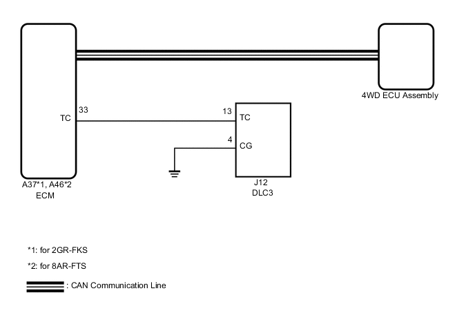
DYNAMIC TORQUE CONTROL AWD SYSTEM TC and CG Terminal Circuit
DESCRIPTION
Connecting terminals TC and CG of the DLC3 causes the 4WD ECU assembly to display the normal system code ("DIAG AWD FF") or stored DTCs on the multi-information display.
Tech Tips
When each warning light remains blinking, a short to ground in the wiring of terminal TC of the DLC3 or an internal short to ground in an ECU is suspected.
WIRING DIAGRAM
CAUTION / NOTICE / HINT
Note
-
When the 4WD ECU assembly is replaced with a known good one from another vehicle, it is necessary to perform calibration.
-
Before replacing the ECM, refer to Service Bulletin.
PROCEDURE
-
CHECK FOR DTC (CAN COMMUNICATION SYSTEM)
-
Check for CAN communication DTCs.
Result Result Proceed to CAN communication system DTCs are not output A CAN communication system DTCs are output B
B 
GO TO CAN COMMUNICATION SYSTEM (HOW TO PROCEED WITH TROUBLESHOOTING) Click here
A 
-
-
INSPECT DLC3
-
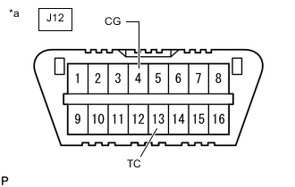
*a Front view of DLC3 Turn the engine switch on (IG).
-
Measure the voltage according to the value(s) in the table below.
Standard Voltage Tester Connection Switch Condition Specified Condition J12-13 (TC) - J12-4 (CG) Engine switch on (IG) 11 to 14 V Result Proceed to OK NG
NG 
CHECK HARNESS AND CONNECTOR (TC OF DLC3 - TC OF ECM AND BODY GROUND) Click here
OK
-
-
REPLACE ECM
-
*a Front view of DLC3 Replace the ECM.
for 8AR-FTS: Click here
for 2GR-FKS: Click here
-
Using SST, connect terminals 13 (TC) and 4 (CG) of the DLC3.
- SST
- 09843-18040
-
Turn the engine switch on (IG).
-
Check that "DIAG AWD FF" or "DIAG AWD XX (DTC)" is displayed.
Result Result Proceed to "DIAG AWD FF" or "DIAG AWD XX (DTC)" is displayed A "DIAG AWD FF" and "DIAG AWD XX (DTC)" are not displayed B
A
END
B
REPLACE 4WD ECU ASSEMBLY Click here
-
-
CHECK HARNESS AND CONNECTOR (TC OF DLC3 - TC OF ECM AND BODY GROUND)
-
Turn the engine switch off.
-
Disconnect the A37*1 or A46*2 ECM connector.
-
*1: for 2GR-FKS
-
*2: for 8AR-FTS
-
-
Measure the resistance according to the value(s) in the table below.
Standard Resistance for 2GR-FKS: Tester Connection Condition Specified Condition J12-13 (TC) - A37-33 (TC) Always Below 1 Ω J12-13 (TC) or A37-33 (TC) - Body ground Always 10 kΩ or higher for 8AR-FTS: Tester Connection Condition Specified Condition J12-13 (TC) - A46-33 (TC) Always Below 1 Ω J12-13 (TC) or A46-33 (TC) - Body ground Always 10 kΩ or higher Result Proceed to OK NG
NG
REPAIR OR REPLACE HARNESS OR CONNECTOR
OK
-
-
CHECK HARNESS AND CONNECTOR (CG OF DLC3 - BODY GROUND)
-
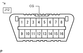
*a Front view of DLC3 Disconnect the A37*1 or A46*2 ECM connector.
-
*1: for 2GR-FKS
-
*2: for 8AR-FTS
-
-
Measure the resistance according to the value(s) in the table below.
Standard Resistance Tester Connection Condition Specified Condition J12-4 (CG) - Body ground Always Below 1 Ω Result Proceed to OK NG
NG
REPAIR OR REPLACE HARNESS OR CONNECTOR
OK
-
-
REPLACE ECM
-
*a Front view of DLC3 Replace the ECM.
for 8AR-FTS: Click here
for 2GR-FKS: Click here
-
Using SST, connect terminals 13 (TC) and 4 (CG) of the DLC3.
- SST
- 09843-18040
-
Turn the engine switch on (IG).
-
Check that "DIAG AWD FF" or "DIAG AWD XX (DTC)" is displayed.
Result Result Proceed to "DIAG AWD FF" or "DIAG AWD XX (DTC)" is displayed A "DIAG AWD FF" and "DIAG AWD XX (DTC)" are not displayed B
A
END
B
REPLACE 4WD ECU ASSEMBLY Click here
-