AUTOMATIC TRANSAXLE UNIT REASSEMBLY

CAUTION / NOTICE / HINT
Tech Tips
Check each bearing position and installation direction.
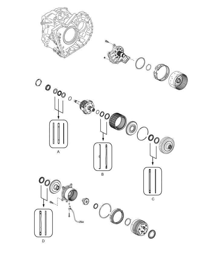
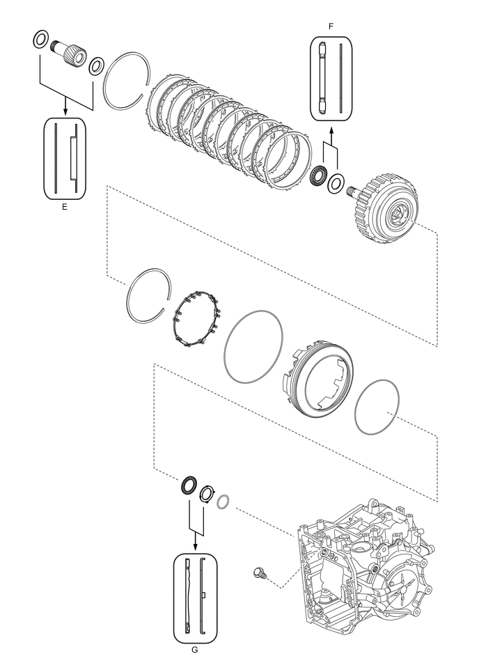
| Mark | Front Thrust Bearing Race Diameter Inside / Outside (mm (in.)) | Thrust Bearing Diameter Inside / Outside (mm (in.)) | Rear Thrust Bearing Race Diameter Inside / Outside (mm (in.)) |
|---|---|---|---|
| A | 31.1 (1.22) / 51 (2.01) | 29.8 (1.17) / 48.8 (1.92) | 29.8 (1.17) / 48.8 (1.92) |
| B | 58.8 (2.31) / 72.7 (2.86) | 57.3 (2.26) / 71.94 (2.83) | - |
| C | - | 39.2 (1.54) / 52.6 (2.07) | 38.1 (1.50) / 50.2 (1.98) |
| D | - | 33.2 (1.31) / 45.6 (1.80) | 35.2 (1.39) / 47 (1.85) |
| E | 33.2 (1.31) / 45.6 (1.80) | - | 25.6 (1.01) / 43.7 (1.72) |
| F | - | 24.25 (0.955) / 41.17 (1.62) | 24.2 (0.953) / 41.7 (1.64) |
| G | - | 50.5 (1.99) / 71.1 (2.80) | 52.8 (2.08) / 76.4 (3.01) |
PROCEDURE
-
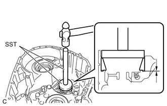
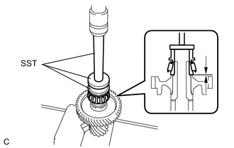
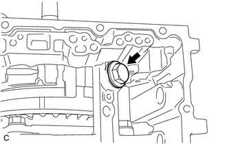
INSTALL COUNTER DRIVEN GEAR TAPERED ROLLER BEARING (FRONT SIDE OUTER RACE)
-
Using SST and a hammer, install a new counter driven gear tapered roller bearing (front side outer race) to the transaxle housing.
- SST
- 09950-60020 ( 09951-00910 )
- 09950-70010 ( 09951-07150 )
Note
Be sure to install the counter driven gear tapered roller bearing (front side outer race) so that there is no clearance between the counter driven gear tapered roller bearing (front side outer race) and the transaxle housing. If there is any clearance, the turning torque of the pinion and counter driven gear sub-assembly cannot be measured correctly.
-
-
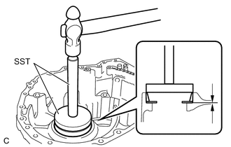
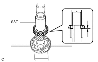
INSTALL DIFFERENTIAL CASE TAPERED ROLLER BEARING (FRONT SIDE OUTER RACE)
-
Using SST and a hammer, install a new differential case tapered roller bearing (front side outer race) to the transaxle housing.
- SST
- 09950-60020 ( 09951-00890 )
- 09950-70010 ( 09951-07200 )
Note
Be sure to install the differential case tapered roller bearing (front side outer race) so that there is no clearance between the differential case tapered roller bearing (front side outer race) and the transaxle housing. If there is any clearance, the turning torque of the differential case assembly cannot be measured correctly.
-
-
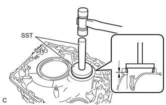
INSTALL COUNTER DRIVEN GEAR TAPERED ROLLER BEARING (REAR SIDE OUTER RACE)
-
Using SST and a hammer, install a new counter driven gear tapered roller bearing (rear side outer race) and shim to the automatic transaxle case sub-assembly.
- SST
- 09950-60010 ( 09951-00680 )
- 09950-70010 ( 09951-07200 )
Note
Be sure to install the counter driven gear tapered roller bearing (rear side outer race) so that there is no clearance between the counter driven gear tapered roller bearing (rear side outer race) and shim, and the automatic transaxle case sub-assembly. If there is any clearance, the turning torque of the pinion and counter driven gear sub-assembly cannot be measured correctly.
-
-
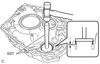
INSTALL DIFFERENTIAL CASE TAPERED ROLLER BEARING (REAR SIDE OUTER RACE)
-
Using SST and a hammer, install a new differential case tapered roller bearing (rear side outer race) and new shim to the automatic transaxle case sub-assembly.
- SST
- 09950-60020 ( 09951-00910 )
- 09950-70010 ( 09951-07150 )
Note
Be sure to install the differential case tapered roller bearing (rear side outer race) so that there is no clearance between the differential case tapered roller bearing (rear side outer race) and shim, and the automatic transaxle case sub-assembly. If there is any clearance, the turning torque of the differential case assembly cannot be measured correctly.
-
-
ADJUST DIFFERENTIAL SIDE BEARING PRELOAD
-
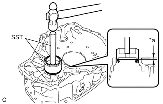
INSTALL TIGHT PLUG (COUNTER DRIVEN GEAR SIDE)
-
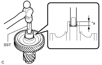
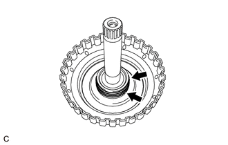
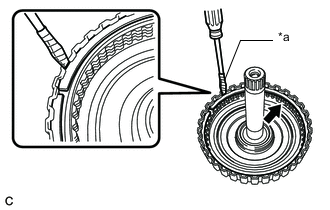
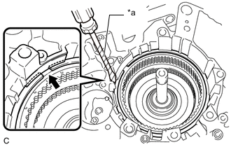
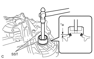
*a Depth Using SST and a hammer, install a new tight plug (counter driven gear side) to the pinion and counter driven gear sub-assembly.
- SST
- 09201-41020
Standard Depth 12.8 to 13.65 mm (0.504 to 0.537 in.)
-
-
INSTALL TIGHT PLUG (DIFFERENTIAL DRIVE PINION SIDE)
-
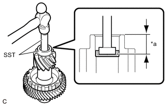
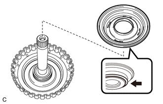
*a Depth Using SST and a hammer, install a new tight plug (differential drive pinion side) to the pinion and counter driven gear sub-assembly.
- SST
- 09950-60010 ( 09951-00260 )
- 09950-70010 ( 09951-07150 )
Standard Depth 25.3 to 26.15 mm (0.996 to 1.03 in.)
-
-
INSTALL COUNTER DRIVEN GEAR TAPERED ROLLER BEARING (REAR SIDE INNER RACE)
-
Using SST and a press, install a new counter driven gear tapered roller bearing (rear side inner race) to the pinion and counter driven gear sub-assembly.
- SST
- 09316-60011 ( 09316-00071 )
- 09950-60010 ( 09951-00560 )
- 09950-70010 ( 09951-07150 )
Note
Be sure to install the counter driven gear tapered roller bearing (rear side inner race) so that there is no clearance between the counter driven gear tapered roller bearing (rear side inner race) and the pinion and counter driven gear sub-assembly. If there is any clearance, the turning torque of the pinion and counter driven gear sub-assembly cannot be measured correctly.
-
-
INSTALL COUNTER DRIVEN GEAR TAPERED ROLLER BEARING (FRONT SIDE INNER RACE)
-
Using SST and a press, install a new counter driven gear tapered roller bearing (front side inner race) to the pinion and counter driven gear sub-assembly.
- SST
- 09636-20010
Note
Be sure to install the counter driven gear tapered roller bearing (front side inner race) so that there is no clearance between the counter driven gear tapered roller bearing (front side inner race) and the pinion and counter driven gear sub-assembly. If there is any clearance, the turning torque of the pinion and counter driven gear sub-assembly cannot be measured correctly.
-
-
ADJUST PINION AND COUNTER DRIVEN GEAR SUB-ASSEMBLY PRELOAD
-
Remove any remaining seal packing from the contact surfaces of the transaxle housing and automatic transaxle case sub-assembly.
-
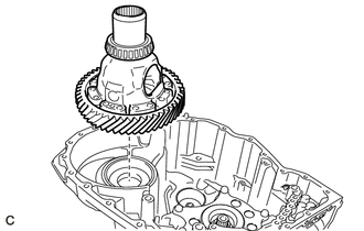
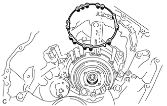
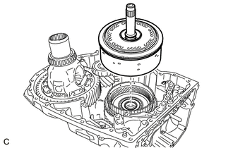
Install the differential case assembly to the automatic transaxle case sub-assembly.
-
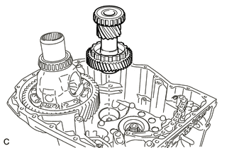
Install the pinion and counter driven gear sub-assembly to the transaxle case sub-assembly.
-
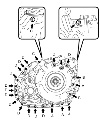
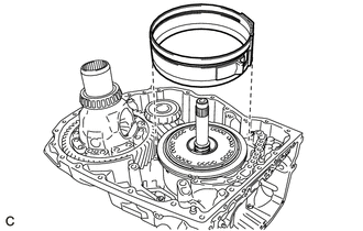
Install the transaxle housing to the automatic transaxle case sub-assembly with the 24 bolts.
- Torque:
- Bolt (A), (B), (D)
- 29 N*m { 296 kgf*cm, 21 ft.*lbf }
- Bolt (C)
- 35 N*m { 357 kgf*cm, 26 ft.*lbf }
Tech Tips
Bolt Length
-
Bolt (A): 30 mm (1.18 in.)
-
Bolt (B): 39 mm (1.54 in.)
-
Bolt (C): 43 mm (1.69 in.)
-
Bolt (D): 35 mm (1.38 in.)
-
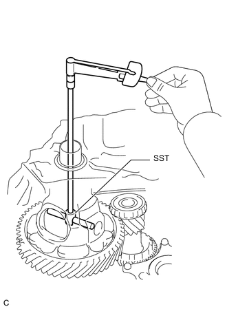
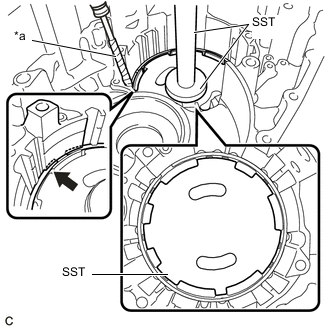
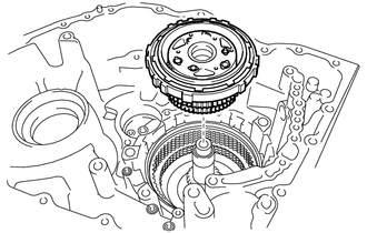
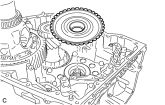
Using SST, turn the differential case assembly right and left 2 or 3 times to settle the bearings.
- SST
- 09564-33010
-
Using SST and a torque wrench, measure the turning torque of the pinion and counter driven gear sub-assembly while rotating SST at 100 rpm.
Turning Torque 0.9 to 3.5 N*m (9 to 36 kgf*cm, 8 to 31 in.*lbf) If the turning torque is not within the specified range, refer to the table below to select a shim so that the turning torque is within the specified range.
Shim Thickness Part Number Thickness
(mm (in.))
Mark 90564-57035 1.19 (0.0469) CA 90564-57036 1.22 (0.0480) CB 90564-57037 1.25 (0.0492) CC 90564-57038 1.28 (0.0504) CD 90564-57039 1.31 (0.0516) CE 90564-57040 1.34 (0.0528) CF 90564-57041 1.37 (0.0539) CG 90564-57042 1.40 (0.0551) CH 90564-57043 1.43 (0.0563) CJ 90564-57044 1.46 (0.0575) CK 90564-57045 1.49 (0.0587) CL 90564-57046 1.52 (0.0598) CM 90564-57047 1.55 (0.0610) CN 90564-57048 1.58 (0.0622) CP 90564-57049 1.61 (0.0634) CR 90564-57050 1.64 (0.0646) CS 90564-57051 1.67 (0.0657) CT 90564-57052 1.70 (0.0669) CU 90564-57053 1.73 (0.0681) CV 90564-57054 1.76 (0.0693) CW 90564-57055 1.79 (0.0705) CX 90564-57056 1.82 (0.0717) CY 90564-57057 1.85 (0.0728) CZ 90564-57058 1.88 (0.0740) DA 90564-57059 1.91 (0.0752) DB 90564-57060 1.94 (0.0764) DC 90564-57061 1.97 (0.0776) DD 90564-57062 2.00 (0.0787) DE 90564-57063 2.03 (0.0799) DF 90564-57064 2.06 (0.0811) DG 90564-57065 2.09 (0.0823) DH 90564-57066 2.12 (0.0835) DJ 90564-57067 2.15 (0.0846) DK 90564-57068 2.18 (0.0858) DL 90564-57069 2.21 (0.0870) DM -
Remove the 24 bolts and transaxle housing from the automatic transaxle case sub-assembly.
Tech Tips
Bolt Length
-
Bolt (A): 30 mm (1.18 in.)
-
Bolt (B): 39 mm (1.54 in.)
-
Bolt (C): 43 mm (1.69 in.)
-
Bolt (D): 35 mm (1.38 in.)
-
-
Remove the pinion and counter driven gear sub-assembly from the transaxle case sub-assembly.
-
Remove the differential case assembly from the automatic transaxle case sub-assembly.
-
-
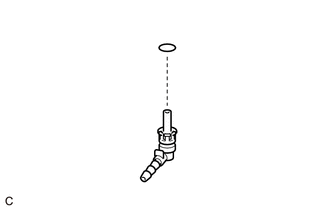
INSTALL NO. 2 TRANSAXLE CASE PLUG
-
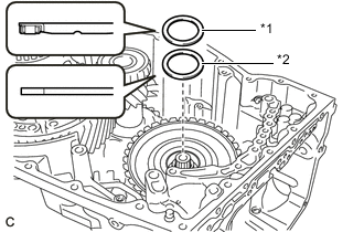
Coat 2 new O-rings with ATF and install them to the 2 No. 2 transaxle case plugs.
Note
Ensure that the 2 O-rings are not twisted.
-
Using a T55 "TORX" socket wrench, install the 2 No. 2 transaxle case plugs to the automatic transaxle case sub-assembly.
- Torque:
- 39 N*m { 398 kgf*cm, 29 ft.*lbf }
-
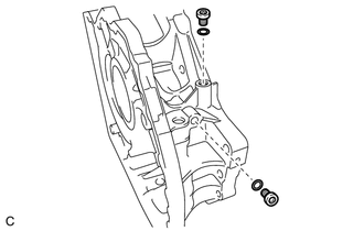
Coat 2 new O-rings with ATF and install them to the 2 No. 2 transaxle case plugs.
Note
Ensure that the 2 O-rings are not twisted.
-
Using a T55 "TORX" socket wrench, install the 2 No. 2 transaxle case plugs to the transaxle housing.
- Torque:
- 39 N*m { 398 kgf*cm, 29 ft.*lbf }
-
-
INSTALL NO. 1 TRANSAXLE CASE PLUG
-
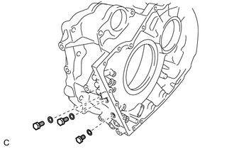
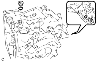
Coat 3 new O-rings with ATF and install them to the 3 No. 1 transaxle case plugs.
Note
Ensure that the 3 O-rings are not twisted.
-
Install the 3 No. 1 transaxle case plugs to the transaxle housing.
- Torque:
- 7.4 N*m { 75 kgf*cm, 65 in.*lbf }
-
Coat 4 new O-rings with ATF and install them to the 4 No. 1 transaxle case plugs.
Note
Ensure that the 4 O-rings are not twisted.
-
Install the 4 No. 1 transaxle case plugs to the automatic transaxle case sub-assembly.
- Torque:
- 7.4 N*m { 75 kgf*cm, 65 in.*lbf }
-
-
INSTALL MANUAL VALVE LEVER SHAFT OIL SEAL
-
Coat the lip of a new manual valve lever shaft oil seal with a small amount of MP grease.
-
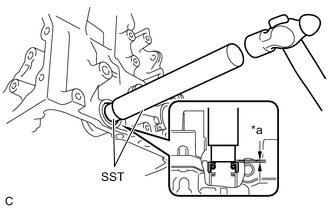
*a Depth Using SST and a hammer, install the manual valve lever shaft oil seal to the automatic transaxle case sub-assembly.
- SST
- 09950-60010 ( 09951-00200 )
- 09950-70010 ( 09951-07150 )
Standard Depth -0.3 to 0.4 mm (-0.0118 to 0.0157 in.)
-
-
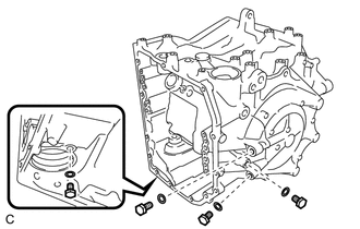
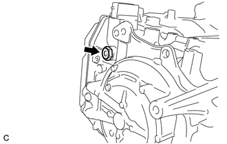
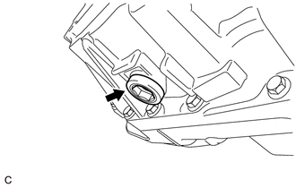
INSTALL BREATHER PLUG
-
Coat a new O-ring with ATF and install it to the breather plug.
Note
Ensure that the O-ring is not twisted.
-
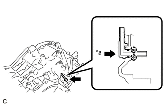
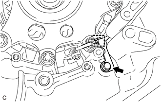
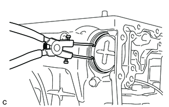
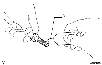
*a Push in Engage each claw to install the breather plug to the automatic transaxle case sub-assembly.
Note
Securely push in the automatic transaxle case sub-assembly until the breather plug is engaged.
-
-
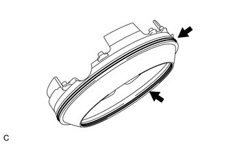
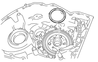
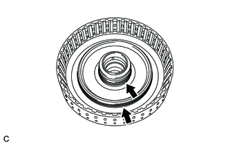
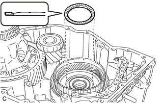
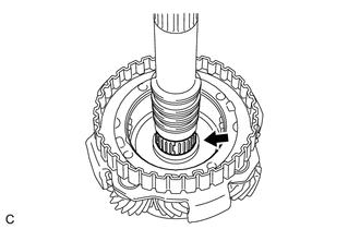
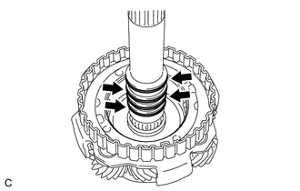
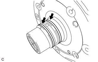
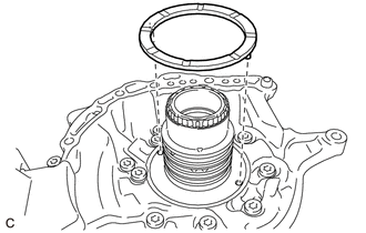
INSTALL DIRECT CLUTCH DRUM OIL SEAL RING
-
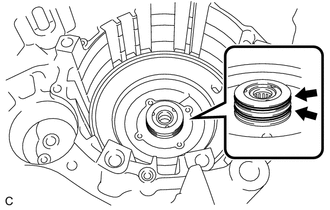
Coat 2 new direct clutch drum oil seal rings with ATF and install them to the automatic transaxle case sub-assembly.
-
-
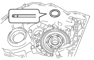
INSTALL NO. 1 THRUST BEARING RACE
-
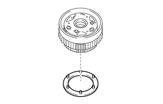
Coat the No. 1 thrust bearing race with ATF and install it to the automatic transaxle case sub-assembly.
No. 1 Thrust Bearing Race Diameter - Inside (mm (in.)) Outside (mm (in.)) No. 1 thrust bearing race 52.8 (2.08) 76.4 (3.01)
-
-
INSTALL 1ST AND REVERSE BRAKE PISTON
-
Coat 2 new O-rings with ATF and install them to the 1st and reverse brake piston.
Note
Ensure that the 2 O-rings are not twisted.
-
Install the 1st and reverse brake piston to the automatic transaxle case sub-assembly.
Note
Be careful not to damage the 2 O-rings.
-
Install the 1st and reverse brake return spring sub-assembly to the 1st and reverse brake piston.
-
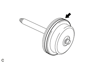
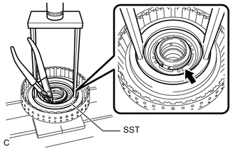
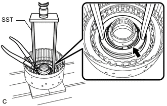
*a Protective Tape Place SST on the 1st and reverse brake return spring sub-assembly and compress it with a press.
- SST
- 09387-00140
- 09950-60010 ( 09951-00650 )
- 09950-70010 ( 09951-07200 )
Note
-
Place SST on the 1st and reverse brake return spring sub-assembly as shown in the illustration.
-
Make sure that SST does not interfere with the 1st and reverse brake piston.
-
Stop pressing when the spring seat is 1 to 2 mm (0.0394 to 0.0787 in.) below the snap ring groove to prevent the spring seat from being deformed.
-
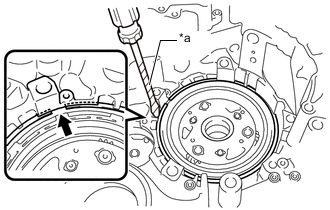
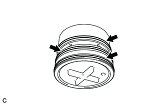
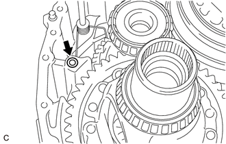
Using a screwdriver with its tip wrapped with protective tape, install the snap ring to the automatic transaxle case sub-assembly.
Note
-
Install the snap ring as shown in the illustration.
-
Be careful not to damage the automatic transaxle case sub-assembly.
-
-
-
INSTALL INTERMEDIATE SHAFT O-RING
-
Coat 2 new intermediate shaft O-rings with ATF and install them to the intermediate shaft sub-assembly.
Note
Ensure that the 2 intermediate shaft O-rings are not twisted.
-
-
INSTALL C-2 CLUTCH PISTON
-
Coat the rubber portion on the edge of the C-2 clutch piston with ATF.
-
Install the C-2 clutch piston to the intermediate shaft sub-assembly.
-
-
INSTALL CLUTCH RETURN WITH RETAINER SPRING SUB-ASSEMBLY
-
Install the clutch return with retainer spring sub-assembly to the intermediate shaft sub-assembly.
-
-
INSTALL C-2 CLUTCH BALANCER
-
Coat the rubber portion on the edge of the C-2 clutch balancer with ATF.
-
Install the C-2 clutch balancer to the intermediate shaft sub-assembly.
-
Place SST on the C-2 clutch balancer and compress the clutch return with retainer spring sub-assembly with a press.
- SST
- 09387-00020
Note
Stop pressing when the spring seat is 1 to 2 mm (0.0394 to 0.0787 in.) below the snap ring groove to prevent the spring seat from being deformed.
-
Using a snap ring expander, install the snap ring to the intermediate shaft sub-assembly.
Note
Do not expand the snap ring excessively.
-
-
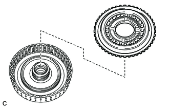
INSTALL NO. 2 CLUTCH DISC
-
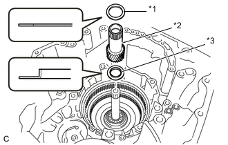
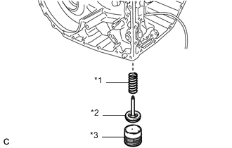
*1 Direct Clutch Flange *2 No. 2 Clutch Disc *3 No. 2 Clutch Plate Install the direct clutch flange, 4 No. 2 clutch discs and 4 No. 2 clutch plates to the intermediate shaft sub-assembly.
Note
Make sure that the direct clutch flange, 4 No. 2 clutch discs and 4 No. 2 clutch plates are installed in the correct order.
-
*a Protective Tape Using a screwdriver with its tip wrapped with protective tape, install the snap ring to the intermediate shaft sub-assembly.
Note
Be careful not to damage the intermediate shaft sub-assembly.
-
-
INSTALL C-2 CLUTCH ASSEMBLY
-
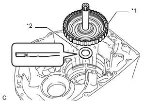
*1 C-2 Clutch Assembly *2 Thrust Needle Roller Bearing Coat the thrust needle roller bearing with ATF and install it to the C-2 clutch assembly.
Thrust Needle Roller Bearing Diameter - Inside (mm (in.)) Outside (mm (in.)) Thrust needle roller bearing 50.5 (1.99) 71.1 (2.80) -
Install the C-2 clutch assembly to the automatic transaxle case sub-assembly.
-
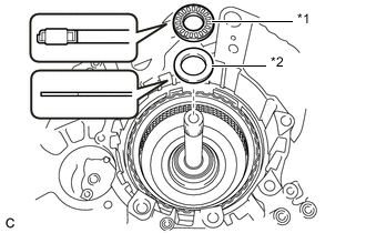
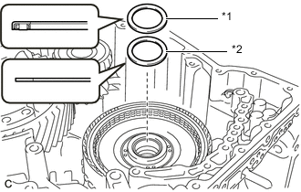
*1 Thrust Needle Roller Bearing *2 No. 2 Thrust Bearing Race Coat the thrust needle roller bearing and No. 2 thrust bearing race with ATF and install them to the C-2 clutch assembly.
Thrust Needle Roller Bearing and No. 2 Thrust Bearing Race Diameter - Inside (mm (in.)) Outside (mm (in.)) Thrust needle roller bearing 24.25 (0.955) 41.17 (1.62) No. 2 thrust bearing race 24.2 (0.953) 41.7 (1.64)
-
-
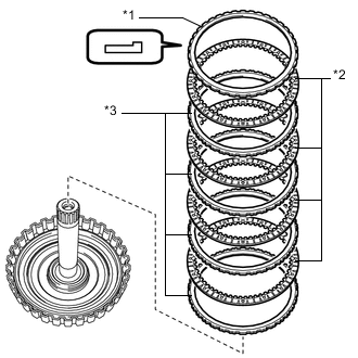
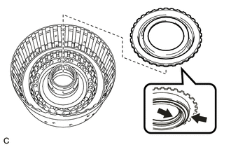
INSTALL 1ST AND REVERSE BRAKE CLUTCH DISC
-
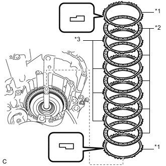
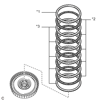
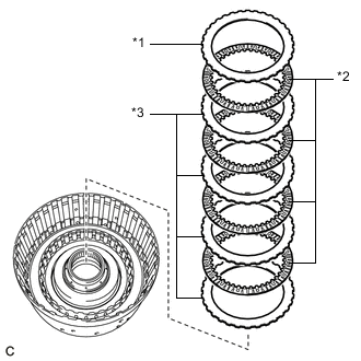
*1 1st and Reverse Brake Flange *2 1st and Reverse Brake Clutch Disc *3 1st and Reverse Brake Clutch Plate Install the 2 1st and reverse brake flanges, 5 1st and reverse brake clutch discs and 4 1st and reverse brake clutch plates to the automatic transaxle case sub-assembly.
Note
-
Make sure that the 2 1st and reverse brake flanges, 5 1st and reverse brake clutch discs and 4 1st and reverse brake clutch plates are installed in the correct order.
-
Be sure to install the 1st and reverse brake flanges in the correct direction as shown in the illustration.
-
-
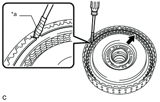
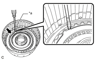
*a Protective Tape Using a screwdriver with its tip wrapped with protective tape, install the snap ring to the automatic transaxle case sub-assembly.
Note
-
Install the snap ring as shown in the illustration.
-
Be careful not to damage the automatic transaxle case sub-assembly.
-
-
-
INSPECT CLEARANCE OF NO. 2 BRAKE
-
INSPECT CLEARANCE OF C-2 CLUTCH
-
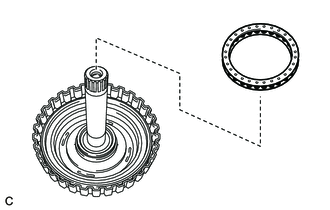
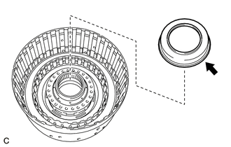
INSTALL REAR PLANETARY SUN GEAR SUB-ASSEMBLY
-
*1 No. 4 Thrust Bearing Race *2 Rear Planetary Sun Gear Sub-assembly *3 No. 3 Thrust Bearing Race Coat the No. 4 thrust bearing race and No. 3 thrust bearing race with ATF and install them to the rear planetary sun gear sub-assembly.
No. 4 Thrust Bearing Race and No. 3 Thrust Bearing Race Diameter - Inside (mm (in.)) Outside (mm (in.)) No. 4 thrust bearing race 33.2 (1.31) 45.6 (1.80) No. 3 thrust bearing race 25.6 (1.01) 43.7 (1.72) -
Install the rear planetary sun gear sub-assembly to the C-2 clutch assembly.
-
-
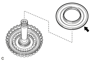
INSTALL REAR PLANETARY GEAR ASSEMBLY
-
Coat the No. 4 planetary carrier thrust washer with ATF and install it to the rear planetary gear assembly.
-
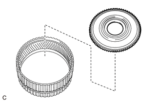
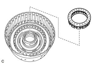
Install the one-way clutch assembly to the rear planetary gear assembly.
-
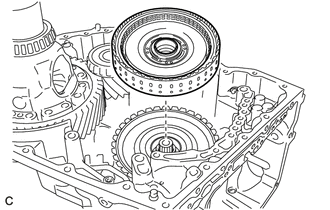
Install the one-way clutch assembly with rear planetary gear assembly to the C-2 clutch assembly.
-
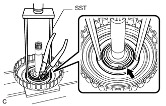
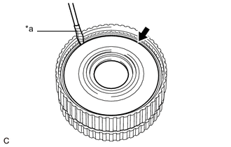
*a Protective Tape Using a screwdriver with its tip wrapped with protective tape, install the snap ring to the automatic transaxle case sub-assembly.
Note
-
Install the snap ring as shown in the illustration.
-
Be careful not to damage the automatic transaxle case sub-assembly.
-
-
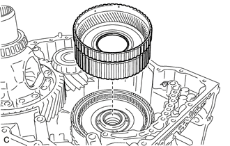
Coat the No. 3 planetary carrier thrust washer with ATF and install it to the rear planetary gear assembly.
-
-
INSTALL PLANETARY SUN GEAR SUB-ASSEMBLY
-
Install the thrust needle roller bearing to the rear planetary gear assembly.
-
Install the planetary sun gear sub-assembly to the rear planetary gear assembly.
-
-
INSTALL FRONT PLANETARY GEAR SUB-ASSEMBLY
-
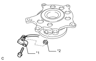
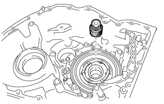
*1 Transmission Revolution Sensor (NC) *2 Spacer Install the transmission revolution sensor (NC) and spacer to the front planetary gear sub-assembly with the bolt.
- Torque:
- 5.4 N*m { 55 kgf*cm, 48 in.*lbf }
-
Install the front planetary gear sub-assembly to the automatic transaxle case sub-assembly.
Note
Be careful not to damage the wire harness.
-
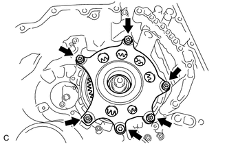
Using a T55 "TORX" socket wrench, install the 6 bolts.
- Torque:
- 62 N*m { 632 kgf*cm, 46 ft.*lbf }
-
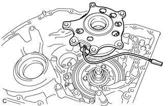
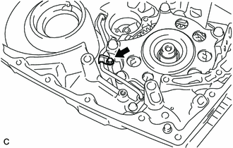
Install the clamp to the automatic transaxle case sub-assembly with the bolt.
- Torque:
- 9.8 N*m { 100 kgf*cm, 87 in.*lbf }
-
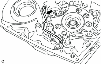
Engage the wire harness clamp.
Note
-
Make sure that the wire harness will not get caught on other components.
-
Remove any slack in the wire harness.
-
-
-
INSTALL B-1 BRAKE PISTON
-
Coat a new O-ring with ATF and install it to the B-1 brake piston.
Note
Ensure that the O-ring is not twisted.
-
Coat 3 new O-rings with ATF and install them to the brake piston cover.
Note
Ensure that the 3 O-rings are not twisted.
-
*1 B-1 Brake Piston Compression Spring *2 B-1 Brake Piston *3 Brake Piston Cover Install the B-1 brake piston compression spring, B-1 brake piston and brake piston cover to the automatic transaxle case sub-assembly.
-
Using snap ring pliers, install the snap ring to the automatic transaxle case sub-assembly.
-
-
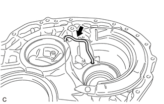
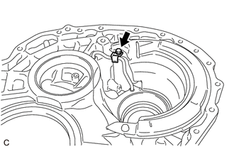
INSTALL TRANSMISSION LUBE APPLY TUBE
-
Install the transmission lube apply tube to the automatic transaxle case sub-assembly.
-
Install the clamp to the automatic transaxle case sub-assembly with the bolt.
- Torque:
- 9.8 N*m { 100 kgf*cm, 87 in.*lbf }
-
-
INSTALL FRONT DRIVE SHAFT OIL SEAL LH
-
Coat the lip of a new front drive shaft oil seal LH with MP grease.
-
*a Depth Using SST and a hammer, install the front drive shaft oil seal LH to the automatic transaxle case sub-assembly.
- SST
- 09316-10010
- 09950-70010 ( 09951-07150 )
Standard Depth -0.5 to 0.5 mm (-0.0197 to 0.0197 in.)
-
-
INSTALL TRANSAXLE CASE OIL SEAL
-
Coat the lip of a new transaxle case oil seal with MP grease.
-
*a Depth Using SST and a hammer, install the transaxle case oil seal to the transaxle housing.
- SST
- 09316-10010
- 09950-70010 ( 09951-07150 )
Standard Depth 5.5 to 6.5 mm (0.217 to 0.256 in.)
-
-
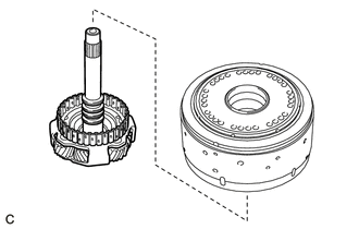
INSTALL DIFFERENTIAL CASE ASSEMBLY
-
Install the differential case assembly to the automatic transaxle case sub-assembly.
-
-
INSTALL PINION AND COUNTER DRIVEN GEAR SUB-ASSEMBLY
-
Install the pinion and counter driven gear sub-assembly to the automatic transaxle case sub-assembly.
-
-
INSTALL INPUT SUN GEAR DRUM
-
Install the input sun gear drum to the rear planetary gear assembly.
-
*1 Thrust Needle Roller Bearing *2 No. 5 Thrust Bearing Race Coat the thrust needle roller bearing and No. 5 thrust bearing race with ATF and install them to the input sun gear drum.
Thrust Needle Roller Bearing and No. 5 Thrust Bearing Race Diameter - Inside (mm (in.)) Outside (mm (in.)) Thrust needle roller bearing 33.2 (1.31) 45.6 (1.80) No. 5 thrust bearing race 35.2 (1.39) 47 (1.85)
-
-
INSTALL C-1 DRUM O-RING
-
Coat 2 new C-1 drum O-rings with ATF and install them to the clutch drum sub-assembly.
Note
Ensure that the 2 C-1 drum O-rings are not twisted.
-
-
INSTALL FORWARD CLUTCH PISTON
-
Coat a new O-ring with ATF and install it to the forward clutch piston.
Note
Ensure that the O-ring is not twisted.
-
Install the forward clutch piston to the clutch drum sub-assembly.
Note
Be careful not to damage the O-ring.
-
-
INSTALL FORWARD CLUTCH RETURN SPRING SUB-ASSEMBLY
-
Install the forward clutch return spring sub-assembly to the clutch drum sub-assembly.
-
-
INSTALL NO. 1 CLUTCH BALANCER
-
Install the No. 1 clutch balancer to the clutch drum sub-assembly.
-
Place SST on the No. 1 clutch balancer and compress the forward clutch return spring sub-assembly with a press.
- SST
- 09387-00020
Note
Stop pressing when the spring seat is 1 to 2 mm (0.0394 to 0.0787 in.) below the snap ring groove to prevent the spring seat from being deformed.
-
Using a snap ring expander, install the snap ring to the clutch drum sub-assembly.
Note
Do not expand the snap ring excessively.
-
-
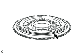
INSTALL FORWARD MULTIPLE DISC CLUTCH DISC
-
*1 Forward Clutch Flange *2 Forward Multiple Disc Clutch Disc *3 Forward Multiple Disc Clutch Plate Install the forward clutch flange, 5 forward multiple disc clutch discs and 5 forward multiple disc clutch plates to the clutch drum sub-assembly.
Note
Make sure that the forward clutch flange, 5 forward multiple disc clutch discs and 5 forward multiple disc clutch plates are installed in the correct order.
-
*a Protective Tape Using a screwdriver with its tip wrapped with protective tape, install the snap ring to the clutch drum sub-assembly.
Note
Be careful not to damage the clutch drum sub-assembly.
-
-
INSPECT CLEARANCE OF C-1 CLUTCH
-
INSTALL C-1 CLUTCH ASSEMBLY
-
Install the C-1 clutch assembly to the rear planetary sun gear sub-assembly.
-
*1 Thrust Needle Roller Bearing *2 No. 6 Thrust Bearing Race Coat the thrust needle roller bearing and No. 6 thrust bearing race with ATF and install them to the C-1 clutch assembly.
Thrust Needle Roller Bearing and No. 6 Thrust Bearing Race Diameter - Inside (mm (in.)) Outside (mm (in.)) Thrust needle roller bearing 39.2 (1.54) 52.6 (2.07) No. 6 thrust bearing race 38.1 (1.50) 50.2 (1.98)
-
-
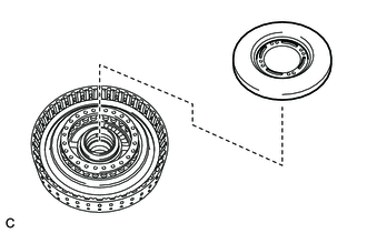
INSTALL FRONT PLANETARY RING GEAR
-
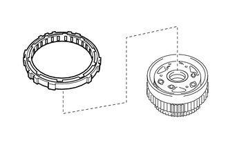
Install the front planetary ring gear flange to the front planetary ring gear.
-
*a Protective Tape Using a screwdriver with its tip wrapped with protective tape, install the snap ring to the front planetary ring gear.
Note
Be careful not to damage the front planetary ring gear.
-
Install the front planetary ring gear with front planetary ring gear flange to the C-1 clutch assembly.
-
Coat the thrust needle roller bearing with ATF and install it to the front planetary ring gear flange.
Thrust Needle Roller Bearing Diameter - Inside (mm (in.)) Outside (mm (in.)) Thrust needle roller bearing 57.3 (2.26) 71.94 (2.83)
-
-
INSTALL FRONT PLANETARY GEAR ASSEMBLY
-
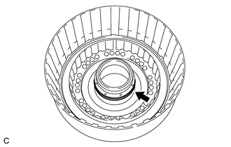
Coat the needle roller bearing with ATF and install it to the front planetary gear assembly.
-
Coat 4 new input shaft oil seal rings with ATF and install them to the front planetary gear assembly.
-
Coat 2 new rear input shaft oil seal rings with ATF and install them to the front planetary gear assembly.
-
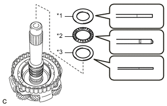
*1 No. 9 Thrust Bearing Race *2 Thrust Needle Roller Bearing *3 No. 8 Thrust Bearing Race Coat the No. 9 thrust bearing race, thrust needle roller bearing and No. 8 thrust bearing race with ATF and install them to the front planetary gear assembly.
No. 9 Thrust Bearing Race, Thrust Needle Roller Bearing and No. 8 Thrust Bearing Race Diameter - Inside (mm (in.)) Outside (mm (in.)) No. 9 thrust bearing race 31.1 (1.22) 51 (2.01) Thrust needle roller bearing 29.8 (1.17) 48.8 (1.92) No. 8 thrust bearing race 29.8 (1.17) 48.8 (1.92) -
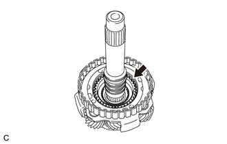
Install the planetary sun gear to the front planetary gear assembly.
-
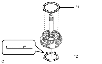
*1 No. 2 Planetary Carrier Thrust Washer *2 No. 7 Thrust Bearing Race Coat the No. 2 planetary carrier thrust washer and No. 7 thrust bearing race with ATF and install them to the front planetary gear assembly.
No. 7 Thrust Bearing Race Diameter - Inside (mm (in.)) Outside (mm (in.)) No. 7 thrust bearing race 58.8 (2.31) 72.7 (2.86)
-
-
INSTALL C-4 CLUTCH BALANCER O-RING
-
Coat a new C-4 clutch balancer O-ring with ATF and install it to the C-3 and C-4 clutch sub-assembly.
Note
Ensure that the C-4 clutch balancer O-ring is not twisted.
-
-
INSTALL C-4 CLUTCH PISTON
-
Coat the rubber portion on the edges of the C-4 clutch piston with ATF.
-
Install the C-4 clutch piston to the C-3 and C-4 clutch sub-assembly.
-
-
INSTALL UNDER DRIVE RETURN WITH RETAINER SPRING SUB-ASSEMBLY
-
Install the under drive return with retainer spring sub-assembly to the C-3 and C-4 clutch sub-assembly.
-
-
INSTALL C-4 CLUTCH BALANCER
-
Coat the rubber portion on the edge of the C-4 clutch balancer with ATF.
-
Install the C-4 clutch balancer to the C-3 and C-4 clutch sub-assembly.
-
Place SST on the C-4 clutch balancer and compress the under drive return with retainer spring sub-assembly with a press.
- SST
- 09387-00020
Note
Stop pressing when the spring seat is 1 to 2 mm (0.0394 to 0.0787 in.) below the snap ring groove to prevent the spring seat from being deformed.
-
Using a snap ring expander, install the snap ring to the C-3 and C-4 clutch sub-assembly.
Note
Do not expand the snap ring excessively.
-
-
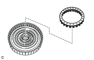
INSTALL NO. 4 CLUTCH DISC
-
*1 No. 1 Underdrive Clutch Flange *2 No. 4 Clutch Disc *3 No. 4 Clutch Plate Install the No. 1 underdrive clutch flange, 4 No. 4 clutch discs and 4 No. 4 clutch plates to the C-3 and C-4 clutch sub-assembly.
Note
Make sure that the No. 1 underdrive clutch flange, 4 No. 4 clutch discs and 4 No. 4 clutch plates are installed in the correct order.
-
*a Protective Tape Using a screwdriver with its tip wrapped with protective tape, install the snap ring to the C-3 and C-4 clutch sub-assembly.
Note
Be careful not to damage the C-3 and C-4 clutch sub-assembly.
-
-
INSTALL NO. 3 CLUTCH DISC
-
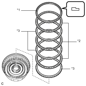
*1 Reverse Clutch Flange *2 No. 3 Clutch Disc *3 No. 3 Clutch Plate Install the reverse clutch flange, 3 No. 3 clutch discs and 3 No. 3 clutch plates to the C-3 and C-4 clutch sub-assembly.
Note
-
Make sure that the 3 No. 3 clutch discs, 3 No. 3 clutch plates and reverse clutch flange are installed in the correct order.
-
Be sure to install the reverse clutch flange in the correct direction as shown in the illustration.
-
-
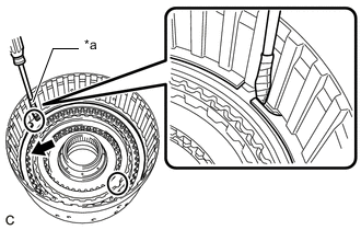
*a Protective Tape Using a screwdriver with its tip wrapped with protective tape, install the snap ring to the C-3 and C-4 clutch sub-assembly.
Note
-
Be careful not to damage the C-3 and C-4 clutch sub-assembly.
-
Make sure that the openings of the No. 4 clutch disc snap ring and No. 3 clutch disc snap ring are positioned 180° apart.
-
-
-
INSPECT CLEARANCE OF C-4 CLUTCH
-
INSPECT CLEARANCE OF C-3 CLUTCH
-
INSTALL C-3 AND C-4 CLUTCH ASSEMBLY
-
Install the C-3 and C-4 clutch assembly to the front planetary gear assembly.
-
Install the C-3 and C-4 clutch assembly with front planetary gear assembly to the automatic transaxle case sub-assembly.
-
Install the B-1 brake band assembly to the C-3 and C-4 clutch drum.
-
Install the bolt to the automatic transaxle case sub-assembly.
- Torque:
- 167 N*m { 1703 kgf*cm, 123 ft.*lbf }
-
-
INSTALL MANUAL VALVE LEVER SUB-ASSEMBLY
-
Install the manual valve lever sub-assembly to the automatic transaxle case sub-assembly.
Note
Do not damage the manual valve lever shaft oil seal while installing the manual valve lever sub-assembly to the automatic transaxle case sub-assembly.
-
-
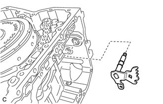
INSTALL PARKING LOCK PIN SUB-ASSEMBLY
-
Coat the parking lock pin sub-assembly with ATF and install it to the automatic transaxle case sub-assembly.
-
-
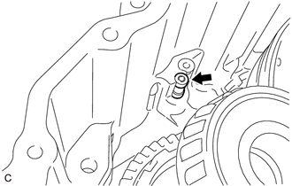
INSTALL PARKING LOCK PAWL
-
Install the parking lock pawl to the automatic transaxle case sub-assembly.
-
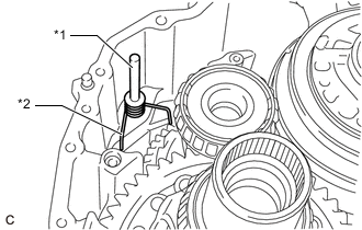
*1 Parking Lock Pawl Shaft *2 Torsion Spring Install the parking lock pawl shaft and torsion spring to the automatic transaxle case sub-assembly.
-
-
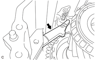
INSTALL PARKING LOCK ROD SUB-ASSEMBLY
-
*1 Parking Lock Pawl *2 Parking Lock Rod Sub-assembly *3 Parking Lock Pin Sub-assembly Align the slot with the notches on the manual valve lever sub-assembly and install the parking lock rod sub-assembly.
-
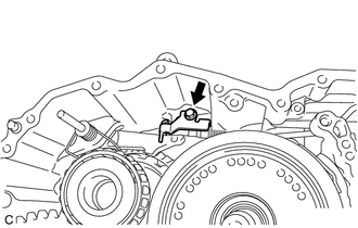
Install the parking lock pawl bracket to the automatic transaxle case sub-assembly with the bolt.
- Torque:
- 9.8 N*m { 100 kgf*cm, 87 in.*lbf }
-
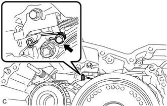
Install the spring guide sleeve and torsion spring to the automatic transaxle case sub-assembly with the bolt.
- Torque:
- 9.8 N*m { 100 kgf*cm, 87 in.*lbf }
-
-
INSTALL MANUAL DETENT SPRING SUB-ASSEMBLY
-
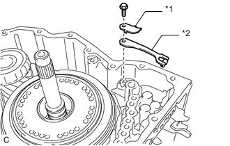
*1 Manual Detent Spring Cover *2 Manual Detent Spring Sub-assembly Install the manual detent spring sub-assembly and manual detent spring cover to the automatic transaxle case sub-assembly with the bolt.
- Torque:
- 9.8 N*m { 100 kgf*cm, 87 in.*lbf }
-
-
INSTALL NO. 1 GOVERNOR APPLY GASKET
-
Coat a new No. 1 governor apply gasket with ATF and install it to the automatic transaxle case sub-assembly.
-
-
INSTALL FRONT OIL PUMP ASSEMBLY
-
Coat the planetary carrier thrust washer with ATF and install it to the front oil pump assembly.
-
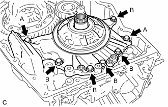
Install the front oil pump assembly to the automatic transaxle case sub-assembly with the 7 bolts.
- Torque:
- 25 N*m { 255 kgf*cm, 18 ft.*lbf }
Tech Tips
Bolt Length
-
Bolt (A): 35 mm (1.38 in.)
-
Bolt (B): 25 mm (0.984 in.)
-
Coat a new front oil pump body O-ring with ATF and install it to the front oil pump assembly.
Note
Ensure that the front oil pump body O-ring is not twisted.
-
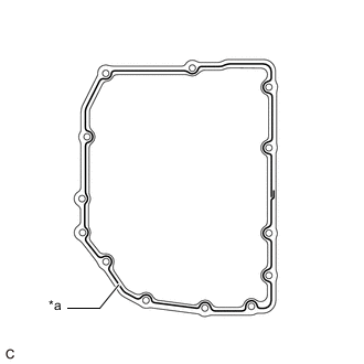
Coat 3 new transaxle case gaskets with ATF and install them to the front oil pump assembly.
-
-
INSPECT B-1 BRAKE PISTON ROD STROKE
-
INSTALL TRANSAXLE HOUSING OIL SEPARATOR
-
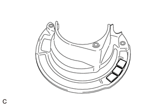
Install the 3 transmission oil cleaner magnets to the transaxle housing oil separator.
-
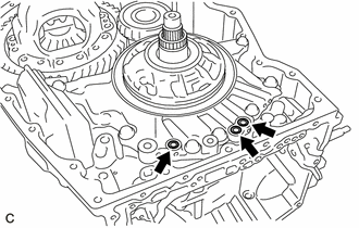
Install the transaxle housing oil separator to the transaxle housing with the 2 bolts.
- Torque:
- 5.4 N*m { 55 kgf*cm, 48 in.*lbf }
Note
If the transaxle housing oil separator is deformed or damaged, replace it with a new one.
-
-
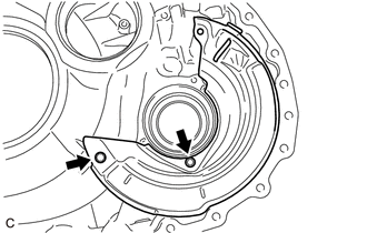
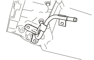
INSTALL DIFFERENTIAL GEAR LUBE APPLY TUBE
-
Install the differential gear lube apply tube to the transaxle housing.
-
Install the clamp to the transaxle housing with the bolt.
- Torque:
- 5.4 N*m { 55 kgf*cm, 48 in.*lbf }
-
-
INSTALL TRANSAXLE HOUSING
-
Remove any remaining seal packing from the sealing surfaces of the transaxle housing and automatic transaxle case sub-assembly.
Note
Make sure that there is no ATF on the sealing surfaces.
-
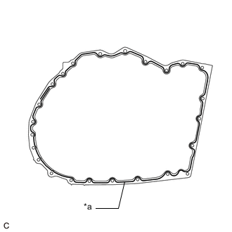
*a FIPG Apply FIPG to the automatic transaxle case sub-assembly.
FIPG Toyota Genuine Seal Packing 1281 Three Bond 1281 or equivalent Note
-
Apply FIPG in a continuous line (width 1.4 mm (0.0551 in.)) along the sealing surface.
-
After applying FIPG, install the transaxle housing to the automatic transaxle case sub-assembly within 3 minutes and tighten the bolts within 20 minutes.
-
-
Install the transaxle housing to the automatic transaxle case sub-assembly with the 24 bolts.
- Torque:
- Bolt (A), (B), (D)
- 29 N*m { 296 kgf*cm, 21 ft.*lbf }
- Bolt (C)
- 35 N*m { 357 kgf*cm, 26 ft.*lbf }
Tech Tips
Bolt Length
-
Bolt (A): 30 mm (1.18 in.)
-
Bolt (B): 39 mm (1.54 in.)
-
Bolt (C): 43 mm (1.69 in.)
-
Bolt (D): 35 mm (1.38 in.)
-
-
INSPECT INPUT SHAFT END PLAY
-
INSTALL TRANSMISSION REVOLUTION SENSOR (NT)
-
INSTALL TRANSMISSION REVOLUTION SENSOR (NC3)
-
INSTALL TRANSMISSION WIRE
-
INSTALL TRANSMISSION VALVE BODY ASSEMBLY
-
INSTALL TRANSMISSION OIL CLEANER MAGNET
-
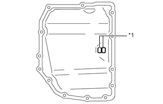
*1 Transmission Oil Cleaner Magnet Install the 2 transmission oil cleaner magnets to the transaxle side cover sub-assembly.
-
-
INSTALL TRANSAXLE SIDE COVER SUB-ASSEMBLY
-
Remove any remaining seal packing from the sealing surface of the automatic transaxle case sub-assembly.
Note
Make sure that there is no ATF on the sealing surface.
-
Clean the 13 bolts and bolt holes in the automatic transaxle case sub-assembly.
-
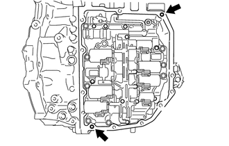
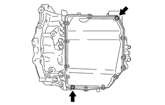
Temporarily install 2 stud bolts to the automatic transaxle case sub-assembly by hand, to the positions shown in the illustration.
Item Part No. Stud Bolt 92122-80825 -
*a FIPG Apply FIPG to a new transaxle side cover sub-assembly.
FIPG Toyota Genuine Seal Packing 1281 Three Bond 1281 or equivalent Note
-
Apply FIPG in a continuous line (width 2.5 mm (0.0984 in.)) along the sealing surface.
-
After applying FIPG, install the transaxle side cover sub-assembly to the automatic transaxle case sub-assembly within 3 minutes and tighten the bolts within 20 minutes.
-
-
*a Adhesive Apply adhesive to 2 or 3 threads on the ends of the 13 bolts.
Adhesive Toyota Genuine Adhesive 1344, Three Bond 1344 or equivalent Note
Make sure to install the bolts immediately after applying adhesive to prevent foreign matter from attaching to them.
-
*a Stud Bolt Using a T40 "TORX" socket wrench, install the transaxle side cover sub-assembly to the automatic transaxle case sub-assembly with the 11 bolts.
- Torque:
- 13 N*m { 133 kgf*cm, 10 ft.*lbf }
-
Remove the 2 stud bolts.
-
Using a T40 "TORX" socket wrench, install the 2 bolts.
- Torque:
- 13 N*m { 133 kgf*cm, 10 ft.*lbf }
-
-
INSTALL TRANSMISSION CASE PLUG ASSEMBLY
-
Install a new transmission case plug assembly to the transaxle housing.
-
-
INSTALL REFILL PLUG
-
Install the refill plug and a new gasket to the automatic transaxle case sub-assembly.
- Torque:
- 49 N*m { 500 kgf*cm, 36 ft.*lbf }
-
-
INSTALL INLET NO. 1 OIL COOLER TUBE SUB-ASSEMBLY
-
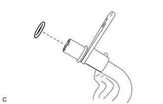
Coat a new O-ring with ATF and install it to the inlet No. 1 oil cooler tube sub-assembly.
Note
Ensure that the O-ring is not twisted.
-
Install the inlet No. 1 oil cooler tube sub-assembly to the transaxle housing.
Note
The installation bolts will be installed after installing the outlet No. 1 oil cooler tube sub-assembly.
-
-
INSTALL OUTLET NO. 1 OIL COOLER TUBE SUB-ASSEMBLY
-
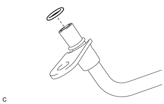
Coat a new O-ring with ATF and install it to the outlet No. 1 oil cooler tube sub-assembly.
Note
Ensure that the O-ring is not twisted.
-
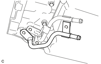
Install the outlet No. 1 oil cooler tube sub-assembly to the transaxle housing.
-
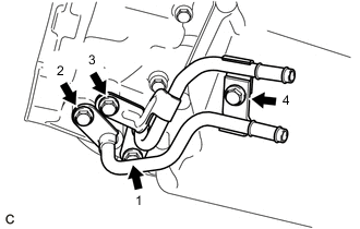
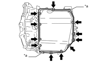
Temporarily install the 4 bolts in the order shown in the illustration.
-
Fully tighten the 4 bolts in the order shown in the illustration.
- Torque:
- 25 N*m { 255 kgf*cm, 18 ft.*lbf }
-
-
INSTALL OVERFLOW PLUG
-
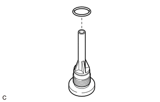
Coat a new O-ring with ATF and install it to the overflow plug.
Note
Ensure that the O-ring is not twisted.
-
Using a 17 mm straight hexagon wrench, install the overflow plug to the transaxle housing.
- Torque:
- 47 N*m { 479 kgf*cm, 35 ft.*lbf }
-
-
INSTALL DRAIN PLUG
-
Coat a new O-ring with ATF and install it to the drain plug.
Note
Ensure that the O-ring is not twisted.
-
Using a T40 "TORX" socket wrench, install the drain plug to the overflow plug.
- Torque:
- 7.4 N*m { 75 kgf*cm, 65 in.*lbf }
-
-
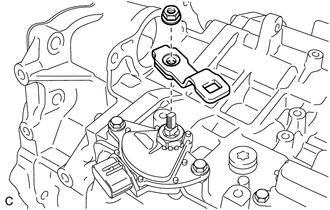
INSTALL PARK/NEUTRAL POSITION SWITCH ASSEMBLY
-
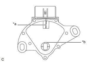
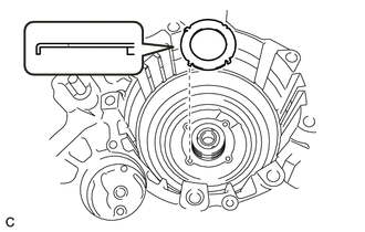
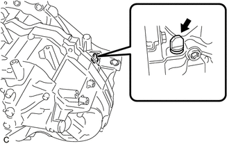
*a Neutral Alignment Mark Line *b Groove Align the groove and the neutral alignment mark line.
-
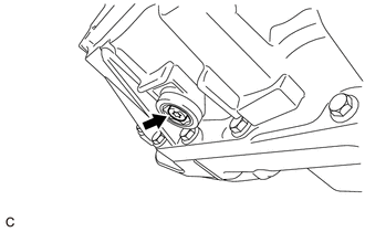
Install the park/neutral position switch assembly to the manual valve lever sub-assembly.
Note
-
Before installing the park/neutral position switch assembly, remove any dirt or foreign matter on the installation portion of the manual valve lever sub-assembly. Be sure to install the park/neutral position switch assembly straight along the manual valve lever sub-assembly while being careful not to deform the plate spring that supports the manual valve lever sub-assembly. If the plate spring is deformed, the park/neutral position switch assembly cannot be reinstalled correctly.
-
After installing the park/neutral position switch assembly, check that the neutral alignment mark line and groove on the park/neutral position switch assembly are aligned.
-
-
Temporarily install the 2 bolts.
-
Install the lock nut and a new lock plate to the manual valve lever sub-assembly.
- Torque:
- 6.9 N*m { 70 kgf*cm, 61 in.*lbf }
-
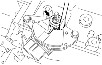
Temporarily install the transmission control shaft lever to the manual valve lever sub-assembly.
-
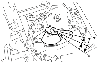
*a P Position *b N Position Turn the transmission control shaft lever clockwise until it stops, and then turn it counterclockwise 2 notches to set it to the N position.
-
Remove the transmission control shaft lever from the manual valve lever sub-assembly.
-
Align the neutral alignment mark line with the park/neutral position switch assembly groove and tighten the 2 bolts.
- Torque:
- 5.4 N*m { 55 kgf*cm, 48 in.*lbf }
-
Using a screwdriver, bend the tabs of the lock plate.
-
-
INSTALL TRANSMISSION CONTROL SHAFT LEVER
-
Install the transmission control shaft lever to the manual valve lever sub-assembly with the nut.
- Torque:
- 16 N*m { 163 kgf*cm, 12 ft.*lbf }
-
-
INSTALL BREATHER PLUG HOSE
-
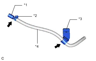
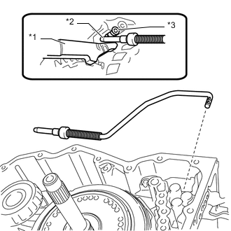
*1 No. 1 Breather Plug (ATM) *2 Breather Hose Clamp *3 Transmission Breather Clamp *4 Breather Plug Hose Install the breather hose clamp and transmission breather clamp to the breather plug hose.
-
Install the No. 1 breather plug (ATM) to the breather plug hose.
-
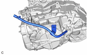
Install the breather plug hose to the breather plug.
-