VALVE BODY ASSEMBLY INSTALLATION
PROCEDURE
-
INSTALL TRANSMISSION VALVE BODY ASSEMBLY
-
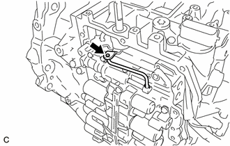
Connect the manual valve connecting rod to the manual valve lever sub-assembly.
-
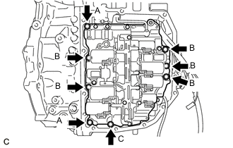
Install the transmission valve body assembly to the automatic transaxle case sub-assembly with the 8 bolts.
- Torque:
- 10 N*m { 102 kgf*cm, 7 ft.*lbf }
Tech Tips
Bolt Length
-
Bolt (A): 31 mm (1.22 in.)
-
Bolt (B): 21 mm (0.827 in.)
-
Bolt (C): 51 mm (2.01 in.)
-
Engage the clamp and guide to connect the transmission revolution sensor (NC) wire.
-
Coat the O-ring of the temperature sensor with ATF.
-
Connect the temperature sensor and install the temperature sensor clamp to the transmission valve body assembly with the bolt.
- Torque:
- 7.0 N*m { 71 kgf*cm, 62 in.*lbf }
-
Connect the 9 shift solenoid valve connectors.
-
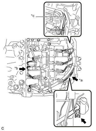
*a Transmission Revolution Sensor (NT) Connector *b Transmission Revolution Sensor (NC) Connector *c Bend wire harness toward automatic transaxle case sub-assembly Connect the transmission revolution sensor (NT) connector and transmission revolution sensor (NC) connector.
Note
Be sure to bend the wire harness toward the automatic transaxle case sub-assembly. If the wire harness is positioned close to the transmission valve body assembly, it may interfere with the manual valve connecting rod.
-
-
INSTALL TRANSAXLE SIDE COVER SUB-ASSEMBLY
-
Remove any remaining seal packing from the sealing surface of the automatic transaxle case sub-assembly.
Note
Make sure that there is no ATF on the sealing surface.
-
Clean the 13 bolts and bolt holes in the automatic transaxle case sub-assembly.
-
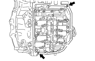
Temporarily install 2 stud bolts to the automatic transaxle case sub-assembly by hand, to the positions shown in the illustration.
Item Part Number Stud Bolt 92122-80825 -
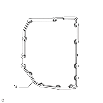
*a FIPG Apply FIPG to a new transaxle side cover sub-assembly.
FIPG Toyota Genuine Seal Packing 1281 Three Bond 1281 or equivalent Note
-
Apply FIPG in a continuous line (width 2.5 mm (0.0984 in.)) along the sealing surface.
-
After applying FIPG, install the transaxle side cover sub-assembly to the automatic transaxle case sub-assembly within 3 minutes and tighten the bolts within 20 minutes.
-
-
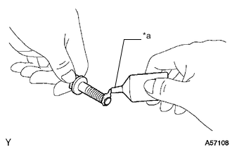
*a Adhesive Apply adhesive to 2 or 3 threads on the ends of the 13 bolts.
Adhesive Toyota Genuine Adhesive 1344, Three Bond 1344 or equivalent Note
Make sure to install the bolts immediately after applying adhesive to prevent foreign matter from attaching to them.
-
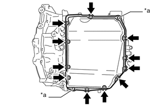
*a Stud Bolt Using a T40 "TORX" socket wrench, install the transaxle side cover sub-assembly to the automatic transaxle case sub-assembly with the 11 bolts.
- Torque:
- 13 N*m { 133 kgf*cm, 10 ft.*lbf }
-
Remove the 2 stud bolts.
-
Using a T40 "TORX" socket wrench, install the 2 bolts.
- Torque:
- 13 N*m { 133 kgf*cm, 10 ft.*lbf }
-
-
INSTALL INLET NO. 1 OIL COOLER TUBE SUB-ASSEMBLY
-
Coat a new O-ring with ATF and install it to the inlet No. 1 oil cooler tube sub-assembly.
Note
Ensure that the O-ring is not twisted.
-
Install the inlet No. 1 oil cooler tube sub-assembly to the transaxle housing.
Note
The installation bolts will be installed after installing the outlet No. 1 oil cooler tube sub-assembly.
-
-
INSTALL OUTLET NO. 1 OIL COOLER TUBE SUB-ASSEMBLY
-
Coat a new O-ring with ATF and install it to the outlet No. 1 oil cooler tube sub-assembly.
Note
Ensure that the O-ring is not twisted.
-
Install the outlet No. 1 oil cooler tube sub-assembly to the transaxle housing.
-
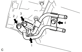
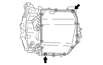
Temporarily install the 4 bolts in the order shown in the illustration.
-
Fully tighten the 4 bolts in the order shown in the illustration.
- Torque:
- 25 N*m { 255 kgf*cm, 18 ft.*lbf }
-
-
INSTALL TORQUE CONVERTER ASSEMBLY
-
INSTALL AUTOMATIC TRANSAXLE ASSEMBLY