OIL COOLER INSTALLATION
PROCEDURE
-
INSTALL TRANSMISSION OIL THERMOSTAT
Tech Tips
Perform this procedure only when replacement of the transmission oil thermostat is necessary.
-
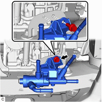
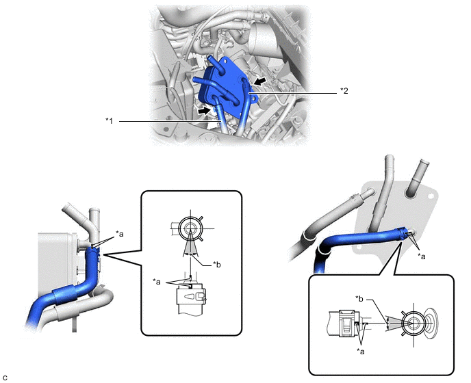
Install the transmission oil thermostat to the transmission oil cooler stay with the bolt as shown in the illustration.
- Torque:
- 19.5 N*m { 199 kgf*cm, 14 ft.*lbf }
-
Connect the outlet oil cooler hose and transmission oil cooler hose to the transmission oil thermostat with each paint mark facing the front of the vehicle and slide the 2 clips to secure them.
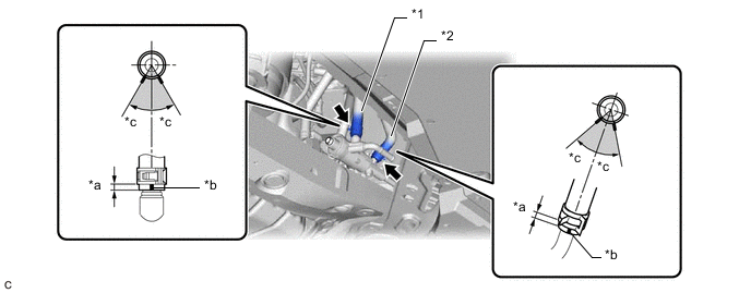
*1 Outlet Oil Cooler Hose *2 Transmission Oil Cooler Hose *a 2 to 7 mm (0.0787 to 0.276 in.) *b Paint Mark *c 30° - - 
Paint Mark Location - - Note
-
Make sure to slide the outlet oil cooler hose and transmission oil cooler hose until each contacts the hose stopper of the transmission oil thermostat.
-
Make sure that each paint mark is within the location shown in the illustration.
-
-
Connect the No. 1 transmission oil cooler hose to the transmission oil thermostat with each paint mark facing up and slide the 2 clips to secure them.
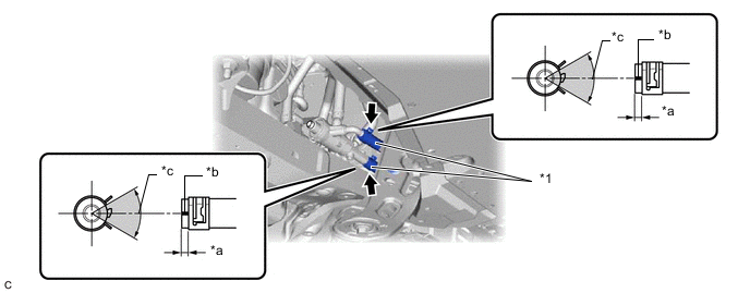
*1 No. 1 Transmission Oil Cooler Hose - - *a 2 to 7 mm (0.0787 to 0.276 in.) *b Paint Mark *c 60° - - Paint Mark Location - - Note
-
Make sure to slide the No. 1 transmission oil cooler hoses until each contacts the hose stopper of the transmission oil thermostat.
-
Make sure that each paint mark is within the location shown in the illustration.
-
-
When replacing the transmission oil thermostat with a new one:
-
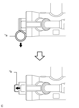
*a Pin *b Shaft Remove the pin from the transmission oil thermostat.
Note
Make sure that the shaft of the transmission oil thermostat protrudes from the cap after removing the pin.
-
-
-
INSTALL TRANSMISSION OIL COOLER
-
Connect the transmission oil cooler hose and inlet oil cooler hose to the transmission oil cooler and slide the 2 clips to secure them.
*1 Transmission Oil Cooler Hose *2 Inlet Oil Cooler Hose *a Paint Mark *b 30° Paint Mark Location - - Note
-
Make sure to connect the transmission oil cooler hose and inlet oil cooler hose to the pipe of the transmission oil cooler with the corresponding color paint mark.
-
Make sure to slide each hose until it contacts the hose stopper of the transmission oil cooler.
-
Make sure that each paint mark is within the location shown in the illustration.
-
-
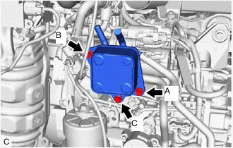
Temporarily install the transmission oil cooler to the front engine mounting bracket with the bolt (A).
-
Install the bolt (B).
- Torque:
- 9.0 N*m { 92 kgf*cm, 80 in.*lbf }
-
Install the bolt (C).
- Torque:
- 9.0 N*m { 92 kgf*cm, 80 in.*lbf }
-
Tighten the bolt (A).
- Torque:
- 9.0 N*m { 92 kgf*cm, 80 in.*lbf }
-
-
CONNECT NO. 5 WATER BY-PASS HOSE
-
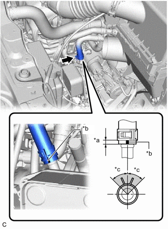
*a 2 to 7 mm (0.0787 to 0.276 in.) *b Paint Mark *c 45° Clip Location Connect the No. 5 water by-pass hose to the transmission oil cooler with the paint mark facing the front of the vehicle and slide the clip to secure it.
Note
-
Make sure to slide the No. 5 water by-pass hose until it contacts the hose stopper of the transmission oil cooler.
-
Make sure that clip is within the location shown in the illustration.
-
-
Engage the water by-pass hose clamp to the No. 5 water by-pass hose.
-
-
CONNECT NO. 3 WATER BY-PASS HOSE
-
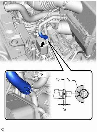
*a 2 to 7 mm (0.0787 to 0.276 in.) *b Paint Mark *c 180° Clip Location Connect the No. 3 water by-pass hose to the transmission oil cooler with the paint mark facing the left of the vehicle and slide the clip to secure it.
Note
-
Make sure to slide the No. 3 water by-pass hose until it contacts the hose stopper of the transmission oil cooler.
-
Make sure that clip is within the location shown in the illustration.
-
-
-
INSTALL BATTERY BRACKET REINFORCEMENT
-
INSTALL BATTERY CARRIER SUB-ASSEMBLY
-
INSTALL BATTERY
-
INSTALL INLET AIR CLEANER ASSEMBLY
-
INSTALL COOL AIR INTAKE DUCT SEAL
-
CONNECT CABLE TO NEGATIVE BATTERY TERMINAL
Note
When disconnecting the cable, some systems need to be initialized after the cable is reconnected.
-
ADD ENGINE COOLANT
-
ADJUST AUTOMATIC TRANSAXLE FLUID
-
INSPECT FOR OIL LEAK
-
INSPECT FOR COOLANT LEAK
-
INSTALL FRONT FENDER APRON SEAL LH
-
INSTALL NO. 3 ENGINE UNDER COVER
-
INSTALL FRONT WHEEL OPENING EXTENSION PAD LH