VALVE BODY ASSEMBLY INSTALLATION
PROCEDURE
-
INSTALL MANUAL VALVE
-
Coat the manual valve with ATF.
-
Install the manual valve to the transmission valve body assembly.
-
-
INSTALL TRANSAXLE CASE GASKET
-
Coat 2 new transaxle case gaskets with ATF.
-
Install the 2 transaxle case gaskets to the transaxle case sub-assembly.
-
-
INSTALL NO. 1 CHECK VALVE SUB-ASSEMBLY
-
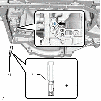
*1 No. 1 Check Valve Sub-assembly *a Ball *b Cage Install the No. 1 check valve sub-assembly to the transaxle case sub-assembly as shown in the illustration.
Note
-
Make sure that the ball of the No. 1 check valve sub-assembly is not stuck before installing the No. 1 check valve sub-assembly.
-
Make sure that the cage of the No. 1 check valve sub-assembly has not fallen off before installing the No. 1 check valve sub-assembly.
-
Be sure to install the No. 1 check valve sub-assembly in the correct direction.
-
Make sure that the No. 1 check valve sub-assembly is fully inserted and does not protrude from the transaxle case sub-assembly.
-
-
-
INSTALL TRANSMISSION VALVE BODY ASSEMBLY
-
Coat the O-ring of the transmission wire with ATF.
-
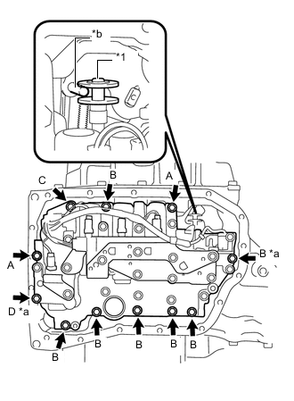
*1 Manual Valve *a Positioning Bolt *b Manual Valve Lever Shaft Sub-assembly Pin Insert the manual valve lever shaft sub-assembly pin into the groove on the end of the manual valve as shown in the illustration and temporarily install the transmission valve body assembly to the transaxle case sub-assembly with the 11 bolts.
Note
-
When installing the transmission valve body assembly, be careful not to allow the transmission revolution sensor and transaxle case sub-assembly to interfere with each other.
-
Be sure to insert the manual valve lever shaft sub-assembly pin into the groove on the end of the manual valve.
-
As the No. 1 check valve sub-assembly is not secured to the transaxle case sub-assembly, be careful when installing the transmission valve body assembly as the No. 1 check valve sub-assembly may fall out.
Tech Tips
-
Bolt (A): 25 mm (0.984 in.)
-
Bolt (B): 30 mm (1.18 in.)
-
Bolt (C): 35 mm (1.38 in.)
-
Bolt (D): 55 mm (2.17 in.)
Bolt Length
-
-
Fully tighten the 2 positioning bolts shown in the illustration.
- Torque:
- 10.8 N*m { 110 kgf*cm, 8 ft.*lbf }
-
Fully tighten the 9 bolts to install the transmission valve body assembly.
- Torque:
- 10.8 N*m { 110 kgf*cm, 8 ft.*lbf }
-
-
INSTALL VALVE BODY OIL STRAINER ASSEMBLY
-
Coat a new O-ring with ATF.
-
Install the O-ring to the valve body oil strainer assembly.
Note
Ensure that the O-ring is not twisted or pinched.
-
Install the valve body oil strainer assembly to the transmission valve body assembly with the 2 bolts.
- Torque:
- 10.8 N*m { 110 kgf*cm, 8 ft.*lbf }
-
-
INSTALL TRANSMISSION OIL CLEANER MAGNET
-
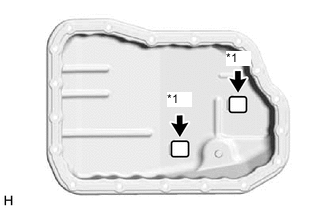
*1 Transmission Oil Cleaner Magnet Install the 2 transmission oil cleaner magnets to the automatic transaxle oil pan sub-assembly as shown in the illustration.
-
-
INSTALL AUTOMATIC TRANSAXLE OIL PAN GASKET
-
Install a new automatic transaxle oil pan gasket to the automatic transaxle oil pan sub-assembly.
-
-
INSTALL AUTOMATIC TRANSAXLE OIL PAN SUB-ASSEMBLY
-
Clean and degrease the bolt and the bolt hole in the transaxle case sub-assembly.
-
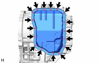
Install the automatic transaxle oil pan sub-assembly with automatic transaxle oil pan gasket to the transaxle case sub-assembly with the 17 bolts.
Note
Completely remove any oil or grease from the contact surfaces of the transaxle case sub-assembly and automatic transaxle oil pan sub-assembly with automatic transaxle oil pan gasket before installation.
- Torque:
- 7.5 N*m { 76 kgf*cm, 66 in.*lbf }
-
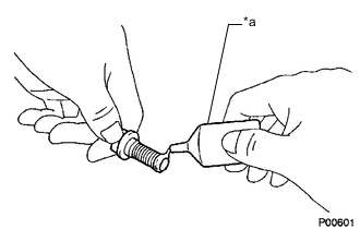
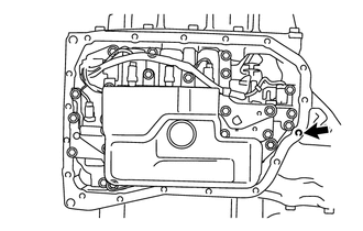
*a Adhesive Apply adhesive to 2 or 3 threads on the end of the bolt.
Adhesive Toyota Genuine Adhesive 1324, Three Bond 1324 or equivalent Note
Make sure to install the bolt immediately after applying adhesive to prevent foreign matter from attaching to it.
-
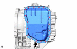
Install the bolt.
- Torque:
- 7.0 N*m { 71 kgf*cm, 62 in.*lbf }
-
-
INSTALL TORQUE CONVERTER ASSEMBLY
-
INSTALL AUTOMATIC TRANSAXLE ASSEMBLY