DYNAMIC RADAR CRUISE CONTROL SYSTEM Distance Control Switch Circuit
DESCRIPTION
The distance control switch is used to set the distance for vehicle-to-vehicle distance control mode. The distance control switch is installed in the steering pad switch assembly. The vehicle-to-vehicle distance set value can be changed by operating the steering pad switch assembly (distance control switch) while the dynamic radar cruise control system is controlling vehicle speed in vehicle-to-vehicle distance control mode.
WIRING DIAGRAM
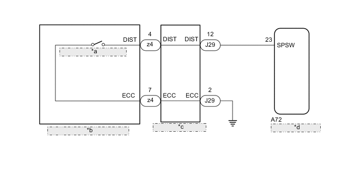
| *a | Distance Control Switch |
| *b | Steering Pad Switch Assembly |
| *c | Spiral Cable Sub-assembly |
| *d | Driving Support ECU Assembly |
CAUTION / NOTICE / HINT
Note
-
Before replacing the ECM, refer to Service Bulletin.
-
The vehicle is equipped with a Supplemental Restraint System (SRS) which includes components such as airbags. Before servicing (including removal or installation of parts), be sure to read the precaution for Supplemental Restraint System.
-
When replacing the driving support ECU assembly, always replace it with a new one. If a driving support ECU assembly which was installed to another vehicle is used, the information stored in the driving support ECU assembly will not match the information from the vehicle. As a result, a DTC may be stored.
PROCEDURE
-
READ VALUE USING GTS (DISTANCE CONTROL SWITCH)
-
Connect the GTS to the DLC3.
-
Turn the engine switch on (IG).
-
Turn the GTS on.
-
Enter the following menus: Powertrain / Radar Cruise 2 / Data List.
-
Read the Data List according to the display on the GTS.
Powertrain > Radar Cruise2 > Data ListTester Display Measurement Item Range Normal Condition Diagnostic Note Distance Control Switch Distance control switch signal ON or OFF ON: Distance control switch on
OFF: Distance control switch off
-
Powertrain > Radar Cruise2 > Data ListTester Display Distance Control Switch OK The Data List item shown in the table changes according to the operation of the steering pad switch assembly (distance control switch). Result Proceed to OK NG
OK 
PROCEED TO NEXT SUSPECTED AREA SHOWN IN PROBLEM SYMPTOMS TABLE Click here
NG 
-
-
INSPECT STEERING PAD SWITCH ASSEMBLY
-
Remove the steering pad switch assembly.
-
Inspect the steering pad switch assembly.
Result Proceed to OK NG
NG
REPLACE STEERING PAD SWITCH ASSEMBLY Click here
OK
-
-
INSPECT SPIRAL CABLE SUB-ASSEMBLY
-
Remove the spiral cable sub-assembly.
-
Inspect the spiral cable sub-assembly.
Result Proceed to OK NG
NG
REPLACE SPIRAL CABLE SUB-ASSEMBLY Click here
OK
-
-
CHECK HARNESS AND CONNECTOR (SPIRAL CABLE SUB-ASSEMBLY - DRIVING SUPPORT ECU ASSEMBLY, ECM AND BODY GROUND)
-
Disconnect the spiral cable sub-assembly connector.
-
Disconnect the driving support ECU assembly connector.
-
Disconnect the ECM connector.
-
Measure the resistance according to the value(s) in the table below.
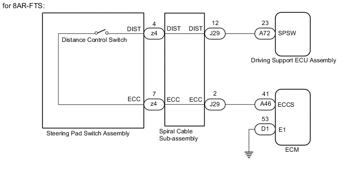
Standard Resistance for 2GR-FKS Tester Connection Condition Specified Condition J29-12 (DIST) - A72-23 (SPSW) Always Below 1 Ω J29-2 (ECC) - Body ground Always Below 1 Ω J29-12 (DIST) or A72-23 (SPSW) - Body ground Always 10 kΩ or higher Standard Resistance for 8AR-FTS Tester Connection Condition Specified Condition J29-12 (DIST) - A72-23 (SPSW) Always Below 1 Ω J29-2 (ECC) - A46-41 (ECCS) Always Below 1 Ω J29-12 (DIST) or A72-23 (SPSW) - Body ground Always 10 kΩ or higher J29-2 (ECC) or A46-41 (ECCS) - Body ground Always 10 kΩ or higher Result Result Proceed to OK (for 2GR-FKS) A OK (for 8AR-FTS) B NG C
A
REPLACE DRIVING SUPPORT ECU ASSEMBLY Click here
C
REPAIR OR REPLACE HARNESS OR CONNECTOR
B
-
-
CHECK HARNESS AND CONNECTOR (ECM - BODY GROUND)
-
Disconnect the D1 ECM connector.
-
Measure the resistance according to the value(s) in the table below.
Standard Resistance Tester Connection Condition Specified Condition D1-53 (E1) - Body ground Always Below 1 Ω Result Proceed to OK NG
NG
REPAIR OR REPLACE HARNESS OR CONNECTOR
OK
-
-
CHECK ECM (ECM TERMINALS)
-
Disconnect the ECM connector.
-
Measure the resistance according to the value(s) in the table below.
Standard Resistance Tester Connection Condition Specified Condition A41-35 (ECCS) - C1-59 (E1) Always Below 1 Ω Result Proceed to OK NG
OK
REPLACE DRIVING SUPPORT ECU ASSEMBLY Click here
NG
REPLACE ECM Click here
-