STARTER REASSEMBLY
PROCEDURE
-
INSTALL PLANETARY GEAR
-
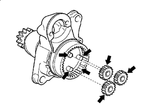

High-temperature Grease Apply high-temperature grease to the 3 planetary gears, 3 planetary gear shafts and starter drive housing assembly.
-
Install the 3 planetary gears to the starter drive housing assembly.
-
-
INSTALL STARTER ARMATURE ASSEMBLY
-
Secure the starter commutator end frame assembly in a vise between aluminum plates.
Note
Do not overtighten the vise.
-
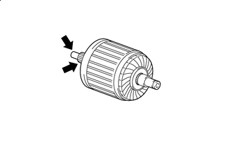
High-temperature Grease Apply high-temperature grease to the starter armature shaft.
-
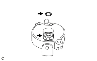
High-temperature Grease Apply high-temperature grease to the washer and bearing shown in the illustration.
-
Install the starter armature assembly to the starter commutator end frame assembly.
-
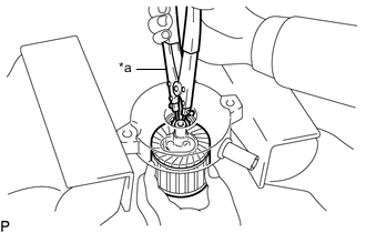
*a Snap Ring Pliers Using snap ring pliers, install the washer and a new snap ring.
Note
-
Be sure to install the snap ring in the starter armature shaft groove securely.
-
Do not expand the snap ring excessively.
-
-
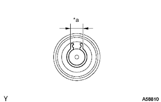
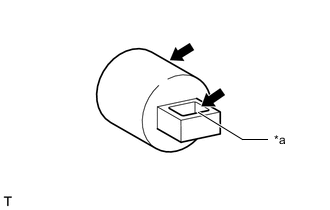
*a Width Using a vernier caliper, measure the width of the snap ring end gap as shown in the illustration.
Maximum Width 5.0 mm (0.197 in.) If the width is greater than the maximum, replace the snap ring with a new one.
-
-
INSTALL STARTER COMMUTATOR END FRAME COVER
-
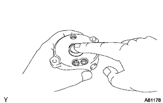
Install the starter commutator end frame cover to the starter commutator end frame assembly.
-
-
INSTALL STARTER ARMATURE PLATE
-
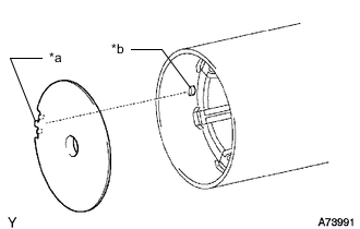
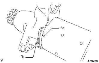
*a Keyway *b Key Insert the starter armature plate to the starter yoke assembly.
-
Align the keyway of the starter armature plate with the key inside the starter yoke assembly, and install the starter armature plate.
-
-
INSTALL STARTER COMMUTATOR END FRAME ASSEMBLY
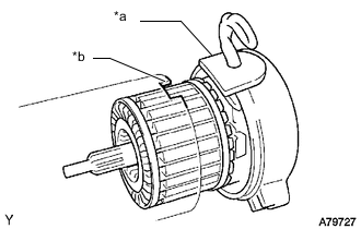
*a Rubber *b Cutout
-
Align the rubber of the starter commutator end frame assembly with the cutout of the starter yoke assembly.
-
Install the starter commutator end frame assembly to the starter yoke assembly.
Note
The magnet of the starter yoke assembly may attract the starter armature assembly when the starter commutator end frame assembly is installed, causing the magnet to break.
-
-
INSTALL STARTER YOKE ASSEMBLY
-
*a Protrusion *b Cutout Align the protrusion of the starter yoke assembly with the cutout of the starter drive housing assembly.
-
Install the starter yoke assembly with the 2 through bolts.
- Torque:
- 6.0 N*m { 61 kgf*cm, 53 in.*lbf }
-
-
INSTALL REPAIR SERVICE STARTER KIT
-
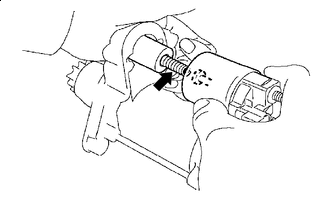
*a Hook High-temperature Grease Apply high-temperature grease to the plunger.
-
Hang the hook of the plunger on the drive lever.
-
High-temperature Grease Apply high-temperature grease to the return spring.
-
Install the return spring to the plunger.
-
Install the magnet switch to the starter drive housing assembly with the 2 screws.
- Torque:
- 7.5 N*m { 76 kgf*cm, 66 in.*lbf }
-
Connect the field coil lead wire to terminal C with the nut.
- Torque:
- 10 N*m { 102 kgf*cm, 7 ft.*lbf }
-