CRUISE CONTROL SYSTEM TERMINALS OF ECU
-
CHECK ECM (for 2GR-FKS)
Tech Tips
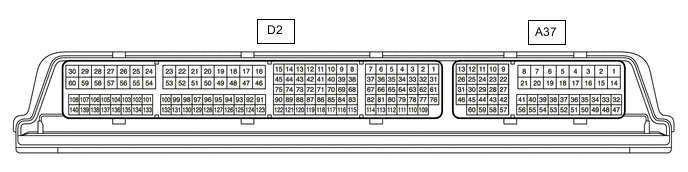
The standard voltage, resistance and waveform between each pair of the ECM terminals is shown in the table below. The appropriate conditions for checking each pair of the terminals is also indicated. The result of checks should be compared with the standard voltage, resistance and waveform for each pair of the terminals as displayed in the Specified Condition column. The illustration above can be used as a reference to identify the ECM terminal locations.
Terminal No. (Symbols) Wiring Color Terminal Description Condition Specified Condition D2-139 (D) - D2-53 (E1) G - BR D shift position signal Engine switch on (IG), shift lever in D 11 to 14 V D2-139 (D) - D2-53 (E1) G - BR D shift position signal Engine switch on (IG), shift lever not in D Below 1 V A37-17 (S) - D2-53 (E1) BR - BR M shift position signal Engine switch on (IG), shift lever in M 11 to 14 V A37-17 (S) - D2-53 (E1) BR - BR M shift position signal Engine switch on (IG), shift lever not in M Below 1 V A37-27 (STP) - D2-53 (E1) B - BR Stop light switch assembly signal Brake pedal depressed 11 to 14 V A37-27 (STP) - D2-53 (E1) B - BR Stop light switch assembly signal Brake pedal released Below 1 V A37-37 (SFTD) - D2-53 (E1) GR - BR Down-shift position switch signal Engine switch on (IG), shift lever in M 11 to 14 V A37-37 (SFTD) - D2-53 (E1) GR - BR Down-shift position switch signal Engine switch on (IG), shift lever in "-" Below 1 V A37-38 (SFTU) - D2-53 (E1) P - BR Up-shift position switch signal Engine switch on (IG), shift lever in M 11 to 14 V A37-38 (SFTU) - D2-53 (E1) P - BR Up-shift position switch signal Engine switch on (IG), shift lever in "+" Below 1 V A37-41 (CCS) - D2-53 (E1) G - BR Cruise control main switch circuit Cruise control main switch (ON/OFF button) not pushed 1 MΩ or higher A37-41 (CCS) - D2-53 (E1) G - BR Cruise control main switch circuit Cruise control main switch (ON/OFF button) pushed Below 2.5 Ω A37-41 (CCS) - D2-53 (E1) G - BR Cruise control main switch circuit +RES switch ON 235 to 245 Ω A37-41 (CCS) - D2-53 (E1) G - BR Cruise control main switch circuit -SET switch ON 617 to 643 Ω A37-41 (CCS) - D2-53 (E1) G - BR Cruise control main switch circuit CANCEL switch ON 1509 to 1571 Ω A37-42 (ST1-) - D2-53 (E1) LG - BR Stop light switch assembly signal Engine switch on (IG), brake pedal depressed Below 1 V A37-42 (ST1-) - D2-53 (E1) LG - BR Stop light switch assembly signal Engine switch on (IG), brake pedal released 11 to 14 V -
CHECK ECM (for 8AR-FTS)
Tech Tips
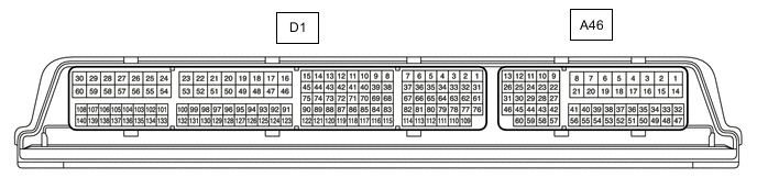
The standard voltage, resistance and waveform between each pair of the ECM terminals is shown in the table below. The appropriate conditions for checking each pair of the terminals is also indicated. The result of checks should be compared with the standard voltage, resistance and waveform for each pair of the terminals as displayed in the Specified Condition column. The illustration above can be used as a reference to identify the ECM terminal locations.
Terminal No. (Symbols) Wiring Color Terminal Description Condition Specified Condition D1-34 (D) - D1-53 (E1) G - BR D shift position signal Engine switch on (IG), shift lever in D 11 to 14 V D1-34 (D) - D1-53 (E1) G - BR D shift position signal Engine switch on (IG), shift lever not in D Below 1 V A46-59 (S) - D1-53 (E1) BR - BR M shift position signal Engine switch on (IG), shift lever in M 11 to 14 V A46-59 (S) - D1-53 (E1) BR - BR M shift position signal Engine switch on (IG), shift lever not in M Below 1 V A46-9 (STP) - D1-53 (E1) B - BR Stop light switch assembly signal Brake pedal depressed 11 to 14 V A46-9 (STP) - D1-53 (E1) B - BR Stop light switch assembly signal Brake pedal released Below 1 V A46-43 (SFTD) - D1-53 (E1) GR - BR Down-shift position switch signal Engine switch on (IG), shift lever in M 11 to 14 V A46-43 (SFTD) - D1-53 (E1) GR - BR Down-shift position switch signal Engine switch on (IG), shift lever in "-" Below 1 V A46-42 (SFTU) - D1-53 (E1) P - BR Up-shift position switch signal Engine switch on (IG), shift lever in M 11 to 14 V A46-42 (SFTU) - D1-53 (E1) P - BR Up-shift position switch signal Engine switch on (IG), shift lever in "+" Below 1 V A46-55 (CCS) - A46-41 (ECCS) G - BR Cruise control main switch circuit Cruise control main switch (ON/OFF button) not pushed 1 MΩ or higher A46-55 (CCS) - A46-41 (ECCS) G - BR Cruise control main switch circuit Cruise control main switch (ON/OFF button) pushed Below 2.5 Ω A46-55 (CCS) - A46-41 (ECCS) G - BR Cruise control main switch circuit +RES switch ON 235 to 245 Ω A46-55 (CCS) - A46-41 (ECCS) G - BR Cruise control main switch circuit -SET switch ON 617 to 643 Ω A46-55 (CCS) - A46-41 (ECCS) G - BR Cruise control main switch circuit CANCEL switch ON 1509 to 1571 Ω A46-10 (ST1-) - D1-53 (E1) LG - BR Stop light switch assembly signal Engine switch on (IG), brake pedal depressed Below 1 V A46-10 (ST1-) - D1-53 (E1) LG - BR Stop light switch assembly signal Engine switch on (IG), brake pedal released 11 to 14 V