WASTE GATE VALVE ACTUATOR ON-VEHICLE INSPECTION
CAUTION / NOTICE / HINT
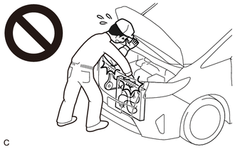
CAUTION:
To prevent injury due to contact with an operating V-ribbed belt or cooling fan, keep your hands and clothing away from the V-ribbed belt and cooling fans when working in the engine compartment with the engine running or the engine switch on (IG).
PROCEDURE
-
INSPECT WASTE GATE VALVE ACTUATOR WITH BRACKET ASSEMBLY
CAUTION:
To prevent injury due to contact with an operating V-ribbed belt or cooling fan, keep your hands and clothing away from the V-ribbed belt and cooling fans when working in the engine compartment with the engine running or the engine switch on (IG).
-
Check that the waste gate valve actuator hose is not cracked or damaged.
-
Check the waste gate valve actuator with bracket assembly air hole.
-
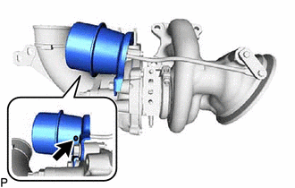
Check that the waste gate valve actuator air hole shown in the illustration is not clogged.
-
-
Check the waste gate valve actuator with bracket assembly travel.
-
Remove the No. 1 exhaust manifold heat insulator.
-
Disconnect the waste gate valve actuator hose.
-
Connect a vacuum pump to the waste gate valve actuator.
-
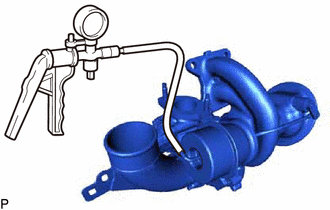
Using the vacuum pump, apply a vacuum of 35 +/- 4.0 kPa (263 +/- 30 mmHg, 10.3 +/- 1.18 in. Hg) to the diaphragm chamber to operate the waste gate valve actuator.
Note
Do not apply a vacuum of 65 kPa (488 mmHg, 19.2 in. Hg) or more to the waste gate valve actuator as doing so may damage the diaphragm.
Tech Tips
If the waste gate valve actuator does not operate, check if the waste gate valve link and waste gate valve actuator are stuck.
-
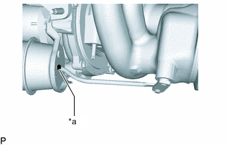
*a Paint Mark Place a paint mark on the waste gate valve actuator rod from the waste gate valve actuator bracket as shown in the illustration.
-
Using a vernier caliper, measure the distance from the waste gate valve actuator bracket to the paint mark at a vacuum of 0 kPa (0 mmHg, 0 in. Hg).
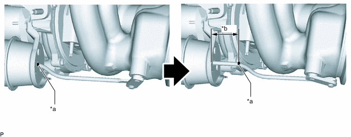
*a Paint Mark *b Travel of Waste Gate Valve Actuator 
Vacuum at 0 kPa (0 mmHg, 0 in. Hg) - - Standard Travel 21.9 to 24.7 mm (0.862 to 0.972 in.) Tech Tips
-
If the travel of the waste gate valve actuator is 21.9 mm (0.862 in.) or less, replace the waste gate valve actuator with bracket assembly.
If the travel of the waste gate valve actuator is 24.7 mm (0.972 in.) or more, check the waste gate valve actuator pin for wear.
-
If the wear of the pin is 0.5 mm (0.0197 in.) or more, replace the waste gate valve actuator with bracket assembly.
If the wear of the pin is 0.5 mm (0.0197 in.) or less, replace the turbine housing with valve sub-assembly.
If the result is not as specified, replace the waste gate valve actuator with bracket assembly and turbine housing with valve sub-assembly, and check the travel of the waste gate valve actuator again.
-
-
Disconnect the vacuum pump from the waste gate valve actuator.
-
Connect the waste gate valve actuator hose.
-
Install the No. 1 exhaust manifold heat insulator.
-
-
Check that the waste gate valve link and waste gate valve actuator is not stuck.
-
Remove the waste gate valve actuator with bracket assembly.
-
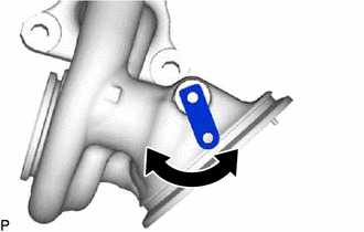
Operate the waste gate valve link by hand and check that the link moves smoothly.
If the waste gate valve link does not move smoothly, replace the turbine housing with valve sub-assembly.
-
Operate the waste gate actuator rod by hand and check that the rod moves smoothly.
If the waste gate waste gate valve actuator rod does not move smoothly, replace the waste gate valve actuator with bracket assembly.
-
Using a vacuum pump, apply a vacuum of 35 +/- 4.0 kPa (263 +/- 30 mmHg, 10.3 +/- 1.18 in. Hg) to the diaphragm chamber to operate the waste gate valve actuator.
Note
Do not apply a vacuum of 65 kPa (488 mmHg, 19.2 in. Hg) or more to the waste gate valve actuator as doing so may damage the diaphragm.
If the waste gate valve actuator does not operate when vacuum is applied, replace the waste gate valve actuator with bracket assembly.
-
Install the waste gate valve actuator with bracket assembly.
-
-
-
ADJUST WASTE GATE VALVE ACTUATOR WITH BRACKET ASSEMBLY
-
Remove the waste gate valve actuator with bracket assembly.
-
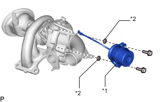
*1 Waste Gate Valve Actuator with Bracket Assembly *2 Plate Washer Install the plate washers between the waste gate valve actuator with bracket assembly and compressor housing with bearing sub-assembly at the positions shown in the illustration to adjust the travel of the waste gate valve actuator.
Tech Tips
Refer to the table below when selecting the appropriate combination plate washers.
Waste Gate Valve Actuator Travel (mm (in.)) Required Plate Washer Thickness (mm (in.)) 21.9 to 24.7 mm (0.862 to 0.972 in.) - 24.7 to 26.2 mm (0.972 to 1.031 in.) 1.6 mm (0.063 in.) 26.2 to 27.7 mm (1.031 to 1.090 in.) 1.6 mm (0.063 in.) 2 Plate Washers -
Install the waste gate valve actuator with bracket assembly.
-
Inspect the travel of the waste gate valve actuator.
-