FUEL TANK(w/o Canister Pump Module) INSTALLATION
PROCEDURE
-
INSTALL TANK SUCTION TUBE SUPPORT
-
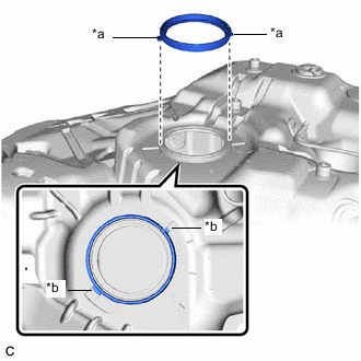
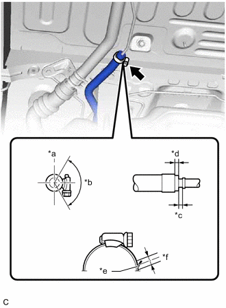
*a Protrusion *b Notch Install a new tank suction tube support to the fuel tank assembly.
Tech Tips
Align the protrusions of the tank suction tube support with the notches of the fuel tank assembly.
-
-
INSTALL FUEL TANK CUSHION SET
-
Install the 2 fuel tank cushion sets and 2 No. 5 fuel tank cushions to the fuel tank assembly.
-
-
INSTALL FUEL TANK TO FILLER PIPE HOSE
-
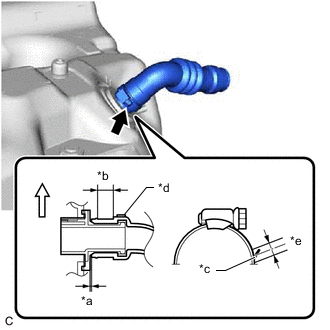
*a 0 to 3.0 mm (0 to 0.118 in.) *b Clamp Area *c Stopper *d Paint Mark *e +/- 2.0 mm (0.0787 in.) 
Up Install the fuel tank to filler pipe hose to the fuel tank assembly and tighten the clamp to secure it.
Tech Tips
-
Make sure the clamp and fuel tank to filler pipe hose are positioned within the area shown in the illustration.
-
Make sure that the clamp end is positioned within 2.0 mm (0.0787 in.) of the stopper.
-
-
-
INSTALL FUEL TANK MAIN TUBE SUB-ASSEMBLY
-
Engage the 3 claws to install the fuel tank main tube sub-assembly to the fuel tank assembly.
-
-
INSTALL REAR FUEL TANK SIDE PLATE
-
Install a new rear fuel tank side plate to the fuel tank assembly with the fuel tank cushion.
-
-
INSTALL FUEL TANK ASSEMBLY
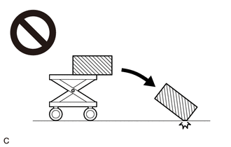
CAUTION:
The fuel tank assembly is very heavy. Be sure to follow the procedure described in the repair manual, or the fuel tank assembly may fall off the engine lifter.
-
Set the fuel tank assembly on an engine lifter.
Tech Tips
Using height adjustment attachments and plate lift attachments, keep the fuel tank assembly horizontal.
-
Using the engine lifter, slowly raise the fuel tank assembly, and then install the fuel tank assembly, No. 1 fuel tank band sub-assembly LH and No. 1 fuel tank band sub-assembly RH with the 4 bolts.
- Torque:
- 45 N*m { 459 kgf*cm, 33 ft.*lbf }
Note
-
Be careful not to drop the fuel tank assembly.
-
When installing the fuel tank assembly, tilt it slightly to prevent it from interfering with the surrounding parts.
-
Install the rear fuel tank bracket LH with the bolt and nut.
- Torque:
- Bolt
- 45 N*m { 459 kgf*cm, 33 ft.*lbf }
- Nut
- 19.6 N*m { 200 kgf*cm, 14 ft.*lbf }
-
Install the nut.
- Torque:
- 19.6 N*m { 200 kgf*cm, 14 ft.*lbf }
-
Connect the fuel cut off valve with tube assembly to the charcoal canister assembly.
-
-
CONNECT FUEL TANK TO FILLER PIPE HOSE
-
*a Up *b 120° *c 0 to 3.0 mm (0 to 0.118 in.) *d Clamp Area *e Stopper *f +/- 2.0 mm (0.0787 in.) *g Alignment Mark (Fuel Tank To Filler Pipe Hose Side) *h Alignment Mark (Fuel Tank To Filler Pipe Side) Connect the fuel tank to filler pipe hose to the fuel tank filler pipe assembly and tighten the clamp to secure it.
Tech Tips
-
Make sure the clamp and fuel tank to filler pipe hose are positioned within the area shown in the illustration.
-
Make sure that the clamp end is positioned within 2.0 mm (0.0787 in.) of the stopper.
-
-
-
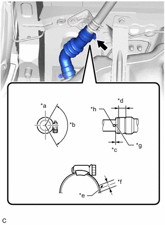
CONNECT FUEL TANK BREATHER TUBE
-
*a Up *b 120° *c 0 to 3.0 mm (0 to 0.118 in.) *d 2.0 to 7.0 mm (0.0787 to 0.276 in.) *e Stopper *f +/- 2.0 mm (0.0787 in.) Connect the fuel tank breather tube to the fuel tank filler pipe assembly and tighten the clamp to secure it.
Tech Tips
-
Make sure the clamp and fuel tank breather tube are positioned within the area shown in the illustration.
-
Make sure that the clamp end is positioned within 2.0 mm (0.0787 in.) of the stopper.
-
-
-
CONNECT FUEL TANK MAIN TUBE SUB-ASSEMBLY
-
Connect the fuel tank main tube sub-assembly to the fuel pipe.
-
-
INSTALL NO. 1 FUEL TANK PROTECTOR SUB-ASSEMBLY
-
Install the No. 1 fuel tank protector sub-assembly with the 7 nuts and 4 new clips.
- Torque:
- 5.5 N*m { 56 kgf*cm, 49 in.*lbf }
-
-
INSTALL CHARCOAL CANISTER PROTECTOR
-
INSTALL FRONT CENTER FLOOR COVER
-
Engage the 4 clips to install the front center floor cover.
-
Install the 2 screws and nut.
-
-
INSTALL REAR SUSPENSION MEMBER SUB-ASSEMBLY (for 2WD)
-
INSTALL REAR SUSPENSION MEMBER SUB-ASSEMBLY (for AWD)
-
INSTALL FUEL SUCTION TUBE WITH PUMP AND GAUGE ASSEMBLY
-
ADD FUEL