ENGINE ASSEMBLY INSTALLATION
CAUTION / NOTICE / HINT
CAUTION:
-
The engine assembly with transaxle is very heavy. Be sure to follow the procedure described in the repair manual, or the engine lifter may suddenly drop or the engine assembly with transaxle may fall off the engine lifter.
-
To prevent burns, do not touch the engine, exhaust manifold or other high temperature components while the engine is hot.
PROCEDURE
-
INSTALL ENGINE MOUNTING INSULATOR LH
Tech Tips
Perform this procedure only when replacement of the engine mounting insulator LH is necessary.
-
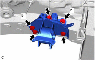
Install the engine mounting insulator LH to the vehicle body with the 5 bolts.
- Torque:
- 71 N*m { 724 kgf*cm, 52 ft.*lbf }
Note
Temporarily tighten the bolt (A), then tighten the bolt (B) before tightening the order 4 bolts.
-
-
INSTALL ENGINE MOUNTING SPACER
Tech Tips
Perform this procedure only when replacement of the engine mounting spacer is necessary.
-
Install the engine mounting spacer to the vehicle body with the 2 bolts.
- Torque:
- 71 N*m { 724 kgf*cm, 52 ft.*lbf }
-
-
INSTALL ENGINE MOUNTING INSULATOR SUB-ASSEMBLY RH
Tech Tips
Perform this procedure only when replacement of the engine mounting insulator sub-assembly RH is necessary.
-
Install the engine mounting insulator sub-assembly RH to the engine mounting spacer and vehicle body with the nut and 2 bolts.
- Torque:
- 71 N*m { 724 kgf*cm, 52 ft.*lbf }
-
Install the brake actuator with bracket to the engine mounting insulator sub-assembly RH with the bolt.
- Torque:
- 19 N*m { 194 kgf*cm, 14 ft.*lbf }
-
Install the cooler bracket to the engine mounting insulator sub-assembly RH with the bolt.
- Torque:
- 9.8 N*m { 100 kgf*cm, 87 in.*lbf }
-
Engage the clamp to the engine mounting insulator sub-assembly RH.
-
-
INSTALL REAR ENGINE MOUNTING INSULATOR
Tech Tips
Perform this procedure only when replacement of the rear engine mounting insulator is necessary.
-
Install the rear engine mounting insulator to the front frame assembly with the 4 nuts.
- Torque:
- 71 N*m { 724 kgf*cm, 52 ft.*lbf }
-
Install the 2 hole plugs to the front frame assembly.
-
-
INSTALL FRONT ENGINE MOUNTING INSULATOR
Tech Tips
Perform this procedure only when replacement of the front engine mounting insulator is necessary.
-
Install the front engine mounting insulator to the front frame assembly with the 3 nuts.
- Torque:
- 52 N*m { 530 kgf*cm, 38 ft.*lbf }
-
Install the hole plug to the front frame assembly.
-
-
INSTALL ENGINE HANGERS
-
REMOVE ENGINE ASSEMBLY FROM ENGINE STAND
-
Remove the engine assembly from the engine stand.
-
-
INSTALL DRIVE PLATE AND RING GEAR SUB-ASSEMBLY
-
INSTALL AUTOMATIC TRANSAXLE ASSEMBLY
for U881E: Click here
for U881F: Click here
-
INSTALL TRANSFER STIFFENER PLATE RH (for AWD)
-
INSTALL STARTER ASSEMBLY
-
INSTALL FRONT ENGINE MOUNTING BRACKET
for U881E: Click here
for U881F: Click here
-
INSTALL FRONT FRAME ASSEMBLY
-
Temporarily install the front engine mounting insulator with front frame assembly to the front engine mounting bracket with the bolt.
-
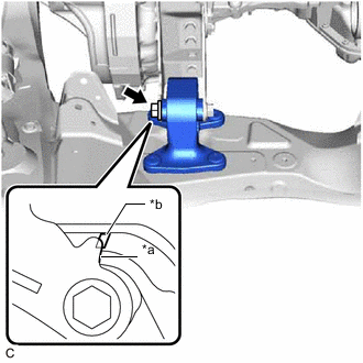
*a Protrusion *b Rib Install the rear engine mounting insulator to the rear engine mounting bracket with the bolt.
- Torque:
- 71 N*m { 724 kgf*cm, 52 ft.*lbf }
Note
If tightening the bolt before installation of the front frame assembly, ensure that the edge of the protrusion of the bracket is within the width of the rib.
-
Fully tighten the bolt of the front engine mounting insulator.
- Torque:
- 87 N*m { 887 kgf*cm, 64 ft.*lbf }
-
-
INSTALL STEERING LINK ASSEMBLY
-
INSTALL FRONT NO. 1 STABILIZER BRACKET LH
-
INSTALL FRONT NO. 1 STABILIZER BRACKET RH
Tech Tips
Perform the same procedure as for the LH side.
-
INSTALL NO. 2 VACUUM SWITCHING VALVE ASSEMBLY
-
INSTALL ENGINE WIRE
-
Connect all connectors and clamps, and install the engine wire to the engine assembly with transaxle.
-
-
INSTALL ENGINE ASSEMBLY WITH TRANSAXLE
-
Using height adjustment attachments and plate lift attachments to keep the engine assembly with transaxle and front frame assembly level, set an engine lifter underneath the engine assembly with transaxle and front frame assembly.
Note
-
Do not perform any procedures while the engine assembly is suspended because doing so may cause the engine assembly to drop, resulting in injury. However, the engine assembly needs to be suspended when it is installed to or removed from an engine stand.
-
To prevent the engine assembly from unexpectedly moving, securely support the engine assembly until it is secured to an engine stand.
-
-
Remove the 4 bolts, No. 1 engine hanger and No. 2 engine hanger.
-
Operate the engine lifter and install the engine assembly with transaxle to the vehicle.
CAUTION:
Do not raise the engine assembly with transaxle more than necessary. If the engine is raised excessively, the vehicle may also be lifted up.
Note
-
Make sure that the engine assembly with transaxle is clear of all wiring and hoses.
-
While raising the engine assembly with transaxle into the vehicle, do not allow it to contact the vehicle.
-
-
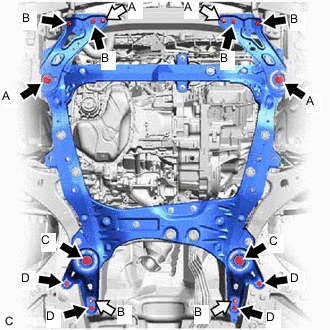

Bolt 
Nut Install the frame side plate sub-assembly RH and frame side plate sub-assembly LH to the front frame assembly and vehicle body with the 6 bolts and 2 nuts.
- Torque:
- Bolt (A)
- 85 N*m { 867 kgf*cm, 63 ft.*lbf }
- Bolt (B) and Nut (A)
- 32 N*m { 326 kgf*cm, 24 ft.*lbf }
-
Install the front suspension member bracket sub-assembly RH and front suspension member bracket sub-assembly LH to the front frame assembly and vehicle body with the 6 bolts and 2 nuts.
- Torque:
- Bolt (C)
- 85 N*m { 867 kgf*cm, 63 ft.*lbf }
- Bolt (D) and Nut (B)
- 32 N*m { 326 kgf*cm, 24 ft.*lbf }
-
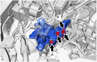
Install the engine mounting insulator sub-assembly RH to the front No. 1 engine mounting bracket LH with the 2 bolts and 2 nuts.
- Torque:
- Bolt and Nut (A)
- 71 N*m { 724 kgf*cm, 52 ft.*lbf }
- Nut (B)
- 40 N*m { 408 kgf*cm, 30 ft.*lbf }
-
Install the No. 2 engine mounting stay RH with the bolt and 2 nuts.
- Torque:
- 20 N*m { 204 kgf*cm, 15 ft.*lbf }
-
Install the engine mounting insulator LH to the engine mounting bracket LH with the bolt and nut.
- Torque:
- 40 N*m { 408 kgf*cm, 30 ft.*lbf }
Note
Tighten the bolt while holding the nut in place.
-
-
INSTALL DRIVE PLATE AND TORQUE CONVERTER ASSEMBLY SETTING BOLT
for U881E: Click here
for U881F: Click here
-
INSTALL FLYWHEEL HOUSING UNDER COVER
-
Install the flywheel housing under cover to the automatic transaxle case sub-assembly with the 2 bolts.
- Torque:
- 10 N*m { 102 kgf*cm, 7 ft.*lbf }
-
-
INSTALL PROPELLER WITH CENTER BEARING SHAFT ASSEMBLY
-
INSTALL FRONT DRIVE SHAFT ASSEMBLY
-
CONNECT STEERING INTERMEDIATE SHAFT ASSEMBLY
-
INSTALL EXHAUST MANIFOLD
-
CONNECT SUCTION HOSE SUB-ASSEMBLY
-
CONNECT DISCHARGE HOSE SUB-ASSEMBLY
-
CONNECT NO. 1 TRANSMISSION OIL COOLER HOSE ASSEMBLY
-
for 2WD:
-
Engage the clamp to connect the No. 1 transmission oil cooler hose assembly to the front No. 2 suspension member dynamic damper.
-
-
for AWD:
-
Connect the No. 1 transmission oil cooler hose assembly to the front frame assembly with the bolt.
- Torque:
- 19.5 N*m { 199 kgf*cm, 14 ft.*lbf }
-
-
-
CONNECT NO. 1 TRANSMISSION OIL COOLER HOSE ASSEMBLY
-
Connect the 2 No. 1 transmission oil cooler hose assemblies and slide the 2 clips to secure them.
-
-
CONNECT UNION TO CHECK VALVE HOSE
for LHD: Click here
for RHD: Click here
-
CONNECT OUTLET HEATER WATER HOSE
-
Connect the outlet heater water hose to the water inlet pipe and slide the clip to secure it.
-
-
CONNECT INLET HEATER WATER HOSE
-
Connect the inlet heater water hose to the water outlet and slide the clip to secure it.
-
Engage the clamp.
-
-
CONNECT NO. 2 RADIATOR HOSE
-
Connect the No. 2 radiator hose to the water inlet and slide the clip to secure it.
-
-
CONNECT NO. 1 RADIATOR HOSE
-
Install the No. 1 radiator hose to the radiator pipe clamp.
-
Connect the No. 1 radiator hose to the water outlet and slide the clip to secure it.
-
-
CONNECT NO. 1 FUEL HOSE
-
Connect the fuel tube sub-assembly (for Port Injection).
-
Connect the fuel tube sub-assembly to the fuel pipe.
-
-
Connect the No. 2 fuel tube sub-assembly (for Direct Injection).
-
Connect the No. 2 fuel tube sub-assembly to the fuel pipe.
-
-
Install the No. 2 fuel pipe clamp to the fuel tube connector.
-
-
CONNECT FUEL VAPOR FEED HOSE ASSEMBLY
-
Connect the fuel vapor feed hose assembly to the No. 1 vacuum switching valve and slide the clip to secure it.
-
-
CONNECT TRANSMISSION CONTROL CABLE ASSEMBLY
for U881E: Click here
for U881F: Click here
-
CONNECT ENGINE WIRE
-
Connect the No. 2 earth wire to the bracket with the bolt.
- Torque:
- 8.4 N*m { 86 kgf*cm, 74 in.*lbf }
-
Engage the clamp and connect the engine wire to the vehicle body.
-
Engage the 2 claws to connect the engine room main wire to the engine wire.
-
Install the engine room main wire with engine wire to the positive (+) battery terminal with the nut.
- Torque:
- 7.6 N*m { 77 kgf*cm, 67 in.*lbf }
-
Engage the clamp and connect the engine wire to the engine mounting insulator LH.
-
Engage the claw and connect the engine wire to the engine room relay block assembly.
-
Install the 2 nuts to the engine mounting insulator LH and vehicle body.
- Torque:
- 8.4 N*m { 86 kgf*cm, 74 in.*lbf }
-
Engage the clamp to the engine room relay block assembly.
-
Connect the engine wire to the vehicle body with the bolt.
- Torque:
- 8.4 N*m { 86 kgf*cm, 74 in.*lbf }
-
Install the nut to the engine room relay block assembly.
- Torque:
- 8.4 N*m { 86 kgf*cm, 74 in.*lbf }
-
Connect the 3 connectors to the engine room relay block assembly.
-
Install the No. 1 relay block cover to the engine room relay block assembly.
-
-
INSTALL ECM
-
INSTALL V-BANK COVER SUB-ASSEMBLY
-
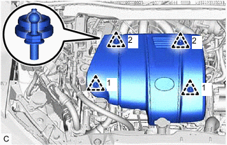
Engage the 4 clips in the order shown in the illustration to install the V-bank cover sub-assembly.
Note
-
Securely engage the clips.
-
If the clips are forcibly engaged or struck with an object, they may be damaged.
-
-
-
INSTALL AIR CLEANER BRACKET
-
Install the air cleaner bracket to the engine mounting insulator LH with the 2 bolts.
- Torque:
- 8.0 N*m { 82 kgf*cm, 71 in.*lbf }
-
-
INSTALL AIR CLEANER CASE SUB-ASSEMBLY
-
Install the air cleaner case sub-assembly to the engine mounting insulator LH and air cleaner bracket with the 2 bolts.
- Torque:
- 5.0 N*m { 51 kgf*cm, 44 in.*lbf }
-
-
INSTALL AIR CLEANER FILTER ELEMENT SUB-ASSEMBLY
-
Install the air cleaner filter element sub-assembly to the air cleaner case sub-assembly.
-
-
INSTALL AIR CLEANER CAP WITH AIR CLEANER HOSE
-
INSTALL INLET AIR CLEANER ASSEMBLY
-
INSTALL COOL AIR INTAKE DUCT SEAL
-
CONNECT CABLE TO NEGATIVE BATTERY TERMINAL
-
ADD ENGINE OIL
-
ADD ENGINE COOLANT
-
CHARGE AIR CONDITIONING SYSTEM WITH REFRIGERANT
-
WARM UP ENGINE
-
INSPECT SHIFT LEVER POSITION
for U881E: Click here
for U881F: Click here
-
ADJUST SHIFT LEVER POSITION
for U881E: Click here
for U881F: Click here
-
INSPECT FOR ENGINE OIL LEAK
-
INSPECT FOR COOLANT LEAK
-
INSPECT FOR AUTOMATIC TRANSAXLE FLUID LEAK
-
INSPECT FOR REFRIGERANT LEAK
-
INSPECT FOR FUEL LEAK
-
INSPECT FOR EXHAUST GAS LEAK
-
CHECK ENGINE OIL LEVEL
-
INSPECT ENGINE COOLANT LEVEL IN RESERVOIR TANK
-
INSTALL FRONT FENDER APRON SEAL RH
-
Install the front fender apron seal RH to the vehicle body with the 2 bolts and clip.
-
-
INSTALL FRONT FENDER APRON SEAL LH
-
Install the front fender apron seal LH to the vehicle body with the 2 bolts and clip.
-
-
INSTALL FRONT FLOOR COVER LH
-
INSTALL NO. 2 ENGINE UNDER COVER
-
Install the No. 2 engine under cover to the front frame assembly with the 2 bolts, 2 screws and clip.
-
-
INSTALL FRONT LOWER BUMPER ABSORBER
-
Engage the 2 claws and install the front lower bumper absorber to the vehicle body with the 4 screws and 2 clips.
-
-
INSTALL NO. 1 ENGINE UNDER COVER
-
Install the No. 1 engine under cover to the vehicle body with the 3 bolts, 2 screws and clip.
-
-
INSTALL FRONT WHEEL OPENING EXTENSION PAD RH
-
Install the front wheel opening extension pad RH to the No. 1 engine under cover with the 2 screws.
-
-
INSTALL NO. 3 ENGINE UNDER COVER
-
Install the No. 3 engine under cover to the vehicle body with the 5 bolts, 2 screws and 2 clips.
-
-
INSTALL FRONT WHEEL OPENING EXTENSION PAD LH
-
Install the front wheel opening extension pad LH to the No. 3 engine under cover with the 2 screws.
-
-
ALIGN FRONT WHEELS FACING STRAIGHT AHEAD
-
INSPECT AND ADJUST FRONT WHEEL ALIGNMENT
-
PERFORM INITIALIZATION
-
INSPECT IGNITION TIMING
-
INSPECT ENGINE IDLE SPEED
-
INSPECT CO/HC
-
CHECK FOR SPEED SENSOR SIGNAL