CAMSHAFT INSTALLATION
PROCEDURE
-
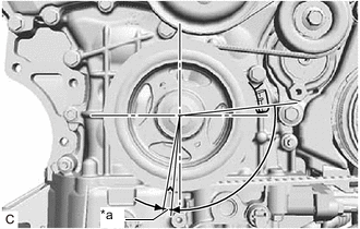
SET NO. 1 CYLINDER TO TDC (COMPRESSION)
-
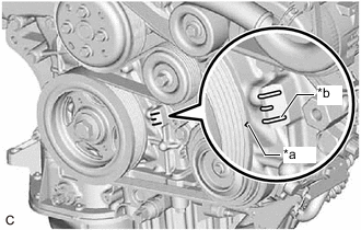
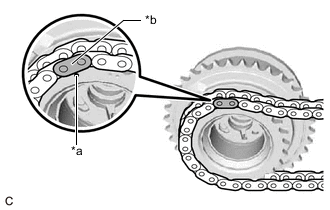
*a Timing Mark (Cutout) *b "0" Timing Mark Confirm that the timing mark (cutout) on the crankshaft pulley is aligned with the "0" timing mark of the timing chain cover assembly.
-
-
SET CAMSHAFT TIMING GEAR ASSEMBLY (for Bank 2)
Tech Tips
Perform Inspection After Repair after replacing the camshaft timing gear assembly.
w/ Canister Pump Module: Click here
w/o Canister Pump Module: Click here
-
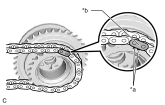
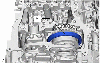
*a Timing Mark *b Mark Plate Align the mark plate (yellow) with the timing mark of the camshaft timing gear assembly as shown in the illustration and install the No. 2 chain sub-assembly to the camshaft timing gear assembly.
-
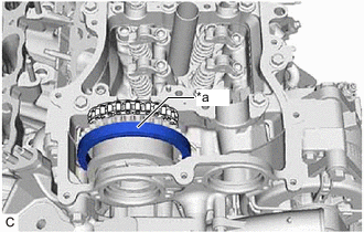
*a Place on camshaft timing gear Install the chain sub-assembly to the camshaft timing gear assembly, and then set the camshaft timing gear assembly to the camshaft housing sub-assembly.
Tech Tips
-
Place the chain sub-assembly on the camshaft timing gear assembly but do not engage the teeth of the sprocket and the chain sub-assembly.
-
Be sure to install the camshaft timing gear assembly with the timing mark facing upward.
-
-
-
SET CAMSHAFT TIMING EXHAUST GEAR ASSEMBLY (for Bank 2)
Tech Tips
Perform Inspection After Repair after replacing the camshaft timing exhaust gear assembly.
w/ Canister Pump Module: Click here
w/o Canister Pump Module: Click here
-
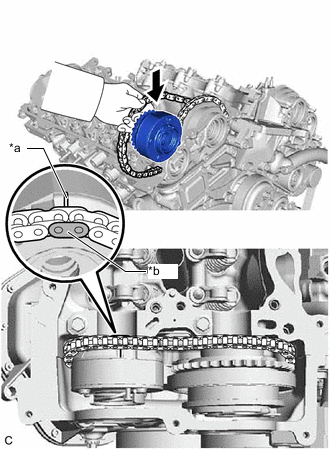
*a Timing Mark *b Mark Plate Align the mark plate (yellow) with the timing mark of the camshaft timing exhaust gear assembly as shown in the illustration and install the No. 2 chain sub-assembly to the camshaft timing exhaust gear assembly.
-
Set the camshaft timing exhaust gear assembly to the camshaft housing sub-assembly LH.
-
-
SET NO. 3 CHAIN TENSIONER ASSEMBLY
-
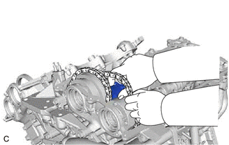
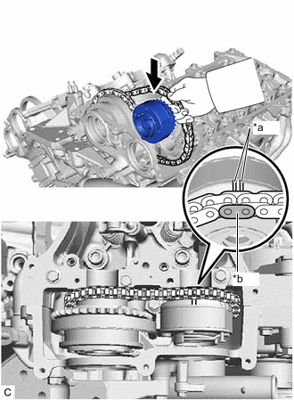
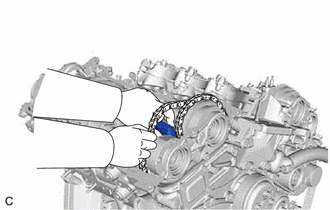
While lifting up the camshaft timing exhaust gear assembly, pass the No. 3 chain tensioner assembly through the No. 2 chain sub-assembly and set it in place.
Note
Temporarily set the No. 3 chain tensioner assembly only, do not install the bolt.
-
-
INSTALL NO. 3 CAMSHAFT SUB-ASSEMBLY
Tech Tips
Perform Inspection After Repair after replacing the No. 3 camshaft sub-assembly.
w/ Canister Pump Module: Click here
w/o Canister Pump Module: Click here
-
Clean the camshaft housing sub-assembly LH and No. 3 camshaft sub-assembly journals and apply engine oil to them.
-
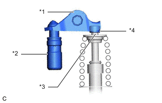
*1 No. 1 Valve Rocker Arm Sub-assembly *2 Valve Lash Adjuster Assembly *3 Valve Stem *4 Valve Stem Cap Make sure that the No. 1 valve rocker arm sub-assembly is installed as shown in the illustration.
-
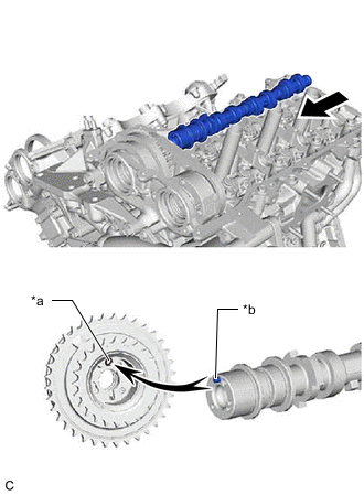
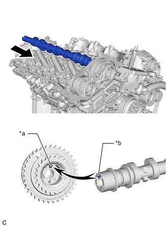
*a Pin Hole *b Straight Pin Align the straight pin of the No. 3 camshaft sub-assembly and the pin hole of the camshaft timing gear assembly, and install the No. 3 camshaft sub-assembly to the camshaft timing gear assembly.
Note
Be careful not to damage the contact surface of the camshaft timing gear assembly with the straight pin of the No. 3 camshaft sub-assembly.
-
Check that there is no clearance between the camshaft timing gear assembly and No. 3 camshaft sub-assembly flange.
-
-
INSTALL NO. 4 CAMSHAFT SUB-ASSEMBLY
Tech Tips
Perform Inspection After Repair after replacing the No. 4 camshaft sub-assembly.
w/ Canister Pump Module: Click here
w/o Canister Pump Module: Click here
-
Clean the camshaft housing LH and No. 4 camshaft sub-assembly journals and apply engine oil to them.
-
*1 No. 1 Valve Rocker Arm Sub-assembly *2 Valve Lash Adjuster Assembly *3 Valve Stem *4 Valve Stem Cap Make sure that the No. 1 valve rocker arm sub-assembly is installed as shown in the illustration.
-
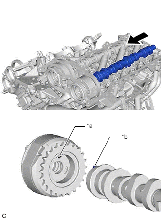
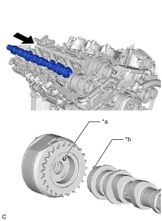
*a Pin Hole *b Straight Pin Align the straight pin of the No. 4 camshaft sub-assembly and the pin hole of the camshaft timing exhaust gear assembly, and install the No. 4 camshaft sub-assembly to the camshaft timing exhaust gear assembly.
Note
Be careful not to damage the contact surface of the camshaft timing exhaust gear assembly with the straight pin of the No. 4 camshaft sub-assembly.
-
Check that there is no clearance between the camshaft timing gear assembly and No. 4 camshaft sub-assembly flange.
-
-
SET CAMSHAFT BEARING CAP (for Bank 2)
-
Clean the camshaft bearing caps and apply engine oil to them.
-
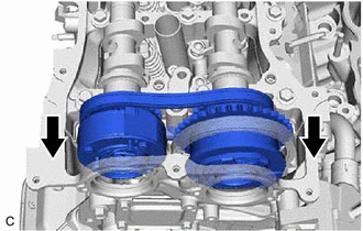
Slide the camshaft timing gear assembly and camshaft timing exhaust gear assembly as shown in the illustration.
Tech Tips
To ensure there is sufficient space for installing the No. 3 camshaft bearing cap and No. 4 camshaft bearing cap, slide the camshaft timing gear assembly and camshaft timing exhaust gear assembly.
-
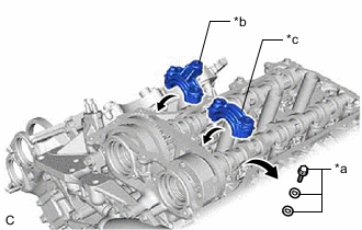
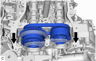
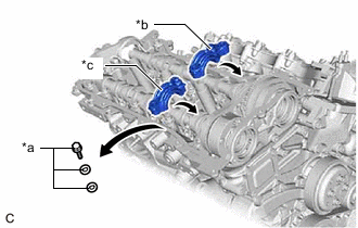
*a Replacement Bolt and Washer *b No. 3 Camshaft Bearing Cap *c No. 4 Camshaft Bearing Cap Remove the replacement bolts and washers (No. 3 camshaft bearing cap and No. 4 camshaft bearing cap side).
Note
Do not remove any of the replacement bolts and washers other than those on the No. 3 camshaft bearing cap and No. 4 camshaft bearing cap side.
-
Temporarily set the No. 3 camshaft bearing cap and No. 4 camshaft bearing cap.
Note
-
Do not install the bolts of the No. 3 camshaft bearing cap and No. 4 camshaft bearing cap.
-
Do not install any camshaft bearing caps other than the No. 3 camshaft bearing cap and No. 4 camshaft bearing cap.
-
-
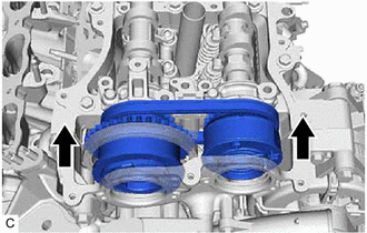
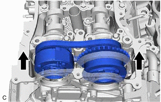
Slide the camshaft timing gear assembly and camshaft timing exhaust gear assembly as shown in the illustration.
Note
Securely insert the straight pins of the No. 3 camshaft sub-assembly and No. 4 camshaft sub-assembly into the pin holes of the camshaft timing gear assembly and camshaft timing exhaust gear assembly.
-
-
TEMPORARILY INSTALL CAMSHAFT TIMING GEAR BOLT (for Intake Side of Bank 2)
Note
There are different types of camshaft timing gear bolts. Make sure to check the identification mark to determine the tightening torque.
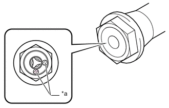
*a Identification Mark Stamp Identification Mark Item Identification Mark Stamp Intake Side Exhaust Side Type A A B Type B D G
-
Check that there is no clearance between the camshaft timing gear assembly and No. 3 camshaft sub-assembly flange.
-
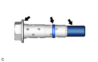
Apply engine oil to the areas of the camshaft timing gear bolt shown in the illustration.
-
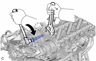
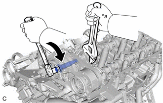
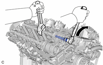
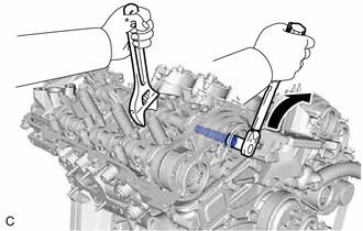
*a Hold 
Turn Use a wrench to hold the hexagonal portion of the No. 3 camshaft sub-assembly.
-
Temporarily install the camshaft timing gear bolt.
- Torque:
- 10 N*m { 102 kgf*cm, 7 ft.*lbf }
Note
-
Installing the camshaft timing gear bolt while there is external force applied to the camshaft timing gear assembly could result in damage to the engine, so make sure that the camshaft bearing cap is not installed when temporarily installing the camshaft timing gear bolt.
-
Be careful not to damage the No. 3 camshaft sub-assembly, camshaft housing sub-assembly LH or spark plug tube with the wrench.
-
Make sure that the flange part of the camshaft timing gear bolt is directly contacting the camshaft timing gear assembly.
-
-
TEMPORARILY INSTALL CAMSHAFT TIMING GEAR BOLT (for Exhaust Side of Bank 2)
Note
There are different types of camshaft timing gear bolts. Make sure to check the identification mark to determine the tightening torque.
*a Identification Mark Stamp Identification Mark Item Identification Mark Stamp Intake Side Exhaust Side Type A A B Type B D G
-
Check that there is no clearance between the camshaft timing exhaust gear assembly and No. 4 camshaft sub-assembly flange.
-
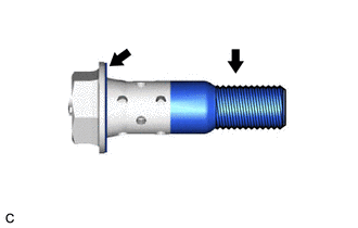
Apply engine oil to the areas of the camshaft timing gear bolt shown in the illustration.
-
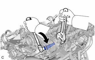
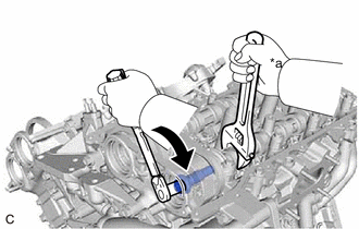
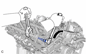
*a Hold Turn Use a wrench to hold the hexagonal portion of the No. 4 camshaft sub-assembly.
-
Temporarily install the camshaft timing gear bolt.
- Torque:
- 10 N*m { 102 kgf*cm, 7 ft.*lbf }
Note
-
Installing the camshaft timing gear bolt while there is external force applied to the camshaft timing exhaust gear assembly could result in damage to the engine, so make sure that the camshaft bearing cap is not installed when temporarily installing the camshaft timing gear bolt.
-
Be careful not to damage the No. 4 camshaft sub-assembly, camshaft housing sub-assembly LH or spark plug tube with the wrench.
-
Make sure that the flange part of the camshaft timing gear bolt is directly contacting the camshaft timing exhaust gear assembly.
-
-
INSTALL CAMSHAFT BEARING CAP (for Bank 2)
-
Clean the camshaft bearing caps and apply engine oil to them.
-
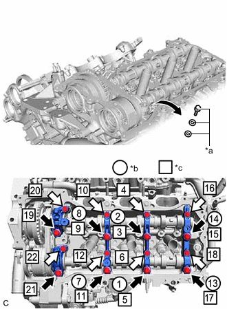
*a Replacement Bolt and Washer *b Replacement Bolt and Washer Removal *c Part Installation Bolt (A) 
Bolt (B) Check the marks and numbers on the camshaft bearing caps, and then remove the replacement bolts and washers in the order shown in the illustration. Immediately after removing the replacement bolts and washers in the location for a camshaft bearing cap, install the camshaft bearing cap with the bolts in the order shown in the illustration.
- Torque:
- Bolt (A)
- 28 N*m { 286 kgf*cm, 21 ft.*lbf }
- Bolt (B)
- 16 N*m { 163 kgf*cm, 12 ft.*lbf }
Note
-
Be sure to follow the numerical order when performing this procedure.
-
Do not drop replacement bolts and washers into the cylinder head LH.
-
Check the torque of each bolt again.
-
-
TIGHTEN CAMSHAFT TIMING GEAR BOLT (for Intake Side of Bank 2)
-
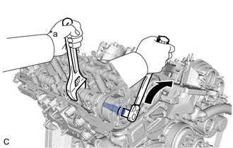
*a Hold Turn Use a wrench to hold the hexagonal portion of the No. 3 camshaft sub-assembly.
-
Tighten the camshaft timing gear bolt.
- Torque:
- Type A
- 120 N*m { 1224 kgf*cm, 89 ft.*lbf }
- Type B
- 95 N*m { 969 kgf*cm, 70 ft.*lbf }
Note
Be careful not to damage the No. 3 camshaft sub-assembly, camshaft housing sub-assembly LH or spark plug tube with the wrench.
-
-
TIGHTEN CAMSHAFT TIMING GEAR BOLT (for Exhaust Side of Bank 2)
-
*a Hold Turn Use a wrench to hold the hexagonal portion of the No. 4 camshaft sub-assembly.
-
Tighten the camshaft timing gear bolt.
- Torque:
- Type A
- 120 N*m { 1224 kgf*cm, 89 ft.*lbf }
- Type B
- 95 N*m { 969 kgf*cm, 70 ft.*lbf }
Note
Be careful not to damage the No. 4 camshaft sub-assembly, camshaft housing sub-assembly LH or spark plug tube with the wrench.
-
-
INSTALL NO. 3 CHAIN TENSIONER ASSEMBLY
-
Install the No. 3 chain tensioner assembly with the bolt.
-
Tighten the bolt.
- Torque:
- 21 N*m { 214 kgf*cm, 15 ft.*lbf }
-
-
CONNECT CHAIN SUB-ASSEMBLY (for Bank 2)
-
*a Paint Mark Align the paint marks on the camshaft timing gear assembly and chain sub-assembly and install the chain sub-assembly to the camshaft timing gear assembly.
Tech Tips
If the paint marks are not aligned, align them by turning the No. 3 camshaft sub-assembly slightly.
-
-
SET CAMSHAFT TIMING GEAR ASSEMBLY (for Bank 1)
Tech Tips
Perform Inspection After Repair after replacing camshaft timing gear assembly.
w/ Canister Pump Module: Click here
w/o Canister Pump Module: Click here
-
*a Timing Mark *b Mark Plate Align the mark plate (yellow) with the timing mark of the camshaft timing gear assembly as shown in the illustration and install the No. 2 chain sub-assembly to the camshaft timing gear assembly.
-
*a Place on camshaft timing gear Install the chain sub-assembly to the camshaft timing gear assembly, and then set the camshaft timing gear assembly to the camshaft housing sub-assembly.
Tech Tips
-
Place the chain sub-assembly on the camshaft timing gear assembly but do not engage the teeth of the sprocket and the chain sub-assembly.
-
Be sure to install the camshaft timing gear assembly with the timing mark facing upward.
-
-
-
SET CAMSHAFT TIMING EXHAUST GEAR ASSEMBLY (for Bank 1)
Tech Tips
Perform Inspection After Repair after replacing the camshaft timing exhaust gear assembly.
w/ Canister Pump Module: Click here
w/o Canister Pump Module: Click here
-
*a Timing Mark *b Mark Plate Align the mark plate (yellow) with the timing mark of the camshaft timing exhaust gear assembly as shown in the illustration and install the No. 2 chain sub-assembly to the camshaft timing exhaust gear assembly.
-
Set the camshaft timing exhaust gear assembly to the camshaft housing sub-assembly.
-
-
SET NO. 2 CHAIN TENSIONER ASSEMBLY
-
While lifting up the camshaft timing exhaust gear assembly, pass the No. 2 chain tensioner assembly through the No. 2 chain sub-assembly and set it in place.
Note
Temporarily set the No. 2 chain tensioner assembly only, do not install the bolt.
-
-
INSTALL CAMSHAFT
Tech Tips
Perform Inspection After Repair after replacing the camshaft.
w/ Canister Pump Module: Click here
w/o Canister Pump Module: Click here
-
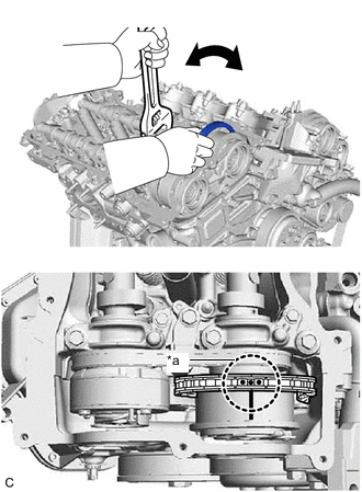
*a 5 to 10° Turn the crankshaft clockwise until it is in the position shown in the illustration so that the chain sub-assembly can be installed easily.
Tech Tips
When turning the crankshaft, engine oil may spray out of the oil holes.
-
Clean the camshaft housing sub-assembly and camshaft journals and apply engine oil to them.
-
*1 No. 1 Valve Rocker Arm Sub-assembly *2 Valve Lash Adjuster Assembly *3 Valve Stem *4 Valve Stem Cap Make sure that the No. 1 valve rocker arm sub-assembly is installed as shown in the illustration.
-
*a Pin Hole *b Straight Pin Align the straight pin of the camshaft and the pin hole of the camshaft timing gear assembly, and install the camshaft to the camshaft timing gear assembly.
Note
Be careful not to damage the contact surface of the camshaft timing gear assembly with the straight pin of the camshaft.
-
Check that there is no clearance between the camshaft timing gear assembly and camshaft flange.
-
-
INSTALL NO. 2 CAMSHAFT
Tech Tips
Perform Inspection After Repair after replacing the No. 2 camshaft.
w/ Canister Pump Module: Click here
w/o Canister Pump Module: Click here
-
Clean the camshaft housing sub-assembly and No. 2 camshaft journals and apply engine oil to them.
-
*1 No. 1 Valve Rocker Arm Sub-assembly *2 Valve Lash Adjuster Assembly *3 Valve Stem *4 Valve Stem Cap Make sure that the No. 1 valve rocker arm sub-assembly is installed as shown in the illustration.
-
*a Pin Hole *b Straight Pin Align the straight pin of the No. 2 camshaft and the pin hole of the camshaft timing exhaust gear assembly, and install the No. 2 camshaft to the camshaft timing exhaust gear assembly.
Note
Be careful not to damage the contact surface of the camshaft timing exhaust gear assembly with the straight pin of the No. 2 camshaft.
-
Check that there is no clearance between the camshaft timing gear assembly flange and No. 2 camshaft.
-
-
SET CAMSHAFT BEARING CAP (for Bank 1)
-
Clean the camshaft bearing caps and apply engine oil to them.
-
Slide the camshaft timing gear assembly and camshaft timing exhaust gear assembly as shown in the illustration.
Tech Tips
To ensure there is sufficient space for installing the No. 1 camshaft bearing cap and No. 2 camshaft bearing cap, slide the camshaft timing gear assembly and camshaft timing exhaust gear assembly.
-
*a Replacement Bolt and Washer *b No. 1 Camshaft Bearing Cap *c No. 2 Camshaft Bearing Cap Remove the replacement bolts and washers (No. 1 camshaft bearing and No. 2 camshaft bearing cap side).
Note
Do not remove any of the replacement bolts and washers other than those on the No. 1 camshaft bearing cap and No. 2 camshaft bearing cap side.
-
Temporarily set the No. 1 camshaft bearing cap and No. 2 camshaft bearing cap.
Note
-
Do not install the bolts of the No. 1 camshaft bearing cap and No. 2 camshaft bearing cap.
-
Do not install any camshaft bearing caps other than the No. 1 camshaft bearing cap and No. 2 camshaft bearing cap.
-
-
Slide the camshaft timing gear assembly and camshaft timing exhaust gear assembly as shown in the illustration.
Note
Securely insert the straight pins of the No. 1 camshaft and No. 2 camshaft into the pin holes of the camshaft timing gear assembly and camshaft timing exhaust gear assembly.
-
-
TEMPORARILY INSTALL CAMSHAFT TIMING GEAR BOLT (for Intake Side of Bank 1)
Note
There are different types of camshaft timing gear bolts. Make sure to check the identification mark to determine the tightening torque.
*a Identification Mark Stamp Identification Mark Item Identification Mark Stamp Intake Side Exhaust Side Type A A B Type B D G
-
Check that there is no clearance between the camshaft timing gear assembly and camshaft flange.
-
Apply engine oil to the areas of the camshaft timing gear bolt shown in the illustration.
-
*a Hold Turn Use a wrench to hold the hexagonal portion of the camshaft.
-
Temporarily install the camshaft timing gear bolt.
- Torque:
- 10 N*m { 102 kgf*cm, 7 ft.*lbf }
Note
-
Installing the camshaft timing gear bolt while there is external force applied to the camshaft timing gear assembly could result in damage to the engine, so make sure that the camshaft bearing cap is not installed when temporarily installing the camshaft timing gear bolt.
-
Be careful not to damage the camshaft, camshaft housing sub-assembly or spark plug tube with the wrench.
-
Make sure that the flange part of the camshaft timing gear bolt is directly contacting the camshaft timing gear assembly.
-
-
TEMPORARILY INSTALL CAMSHAFT TIMING GEAR BOLT (for Exhaust Side of Bank 1)
Note
There are different types of camshaft timing gear bolts. Make sure to check the identification mark to determine the tightening torque.
*a Identification Mark Stamp Identification Mark Item Identification Mark Stamp Intake Side Exhaust Side Type A A B Type B D G
-
Check that there is no clearance between the camshaft timing exhaust gear assembly and No. 2 camshaft flange.
-
Apply engine oil to the areas of the camshaft timing gear bolt shown in the illustration.
-
*a Hold Turn Use a wrench to hold the hexagonal portion of the No. 2 camshaft.
-
Temporarily install the camshaft timing gear bolt.
- Torque:
- 10 N*m { 102 kgf*cm, 7 ft.*lbf }
Note
-
Installing the camshaft timing gear bolt while there is external force applied to the camshaft timing exhaust gear assembly could result in damage to the engine, so make sure that the camshaft bearing cap is not installed when temporarily installing the camshaft timing gear bolt.
-
Be careful not to damage the No. 2 camshaft, camshaft housing sub-assembly or spark plug tube with the wrench.
-
Make sure that the flange part of the camshaft timing gear bolt is directly contacting the camshaft timing exhaust gear assembly.
-
-
INSTALL CAMSHAFT BEARING CAP (for Bank 1)
-
Clean the camshaft bearing caps and apply engine oil to them.
-
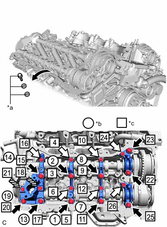
*a Replacement Bolt and Washer *b Replacement Bolt and Washer Removal *c Part Installation Bolt (A) Bolt (B) Check the marks and numbers on the camshaft bearing caps, and then remove the replacement bolts and washers in the order shown in the illustration. Immediately after removing the replacement bolts and washers in the location for a camshaft bearing cap, install the camshaft bearing cap with the bolts in the order shown in the illustration.
- Torque:
- Bolt (A)
- 28 N*m { 286 kgf*cm, 21 ft.*lbf }
- Bolt (B), (C)
- 16 N*m { 163 kgf*cm, 12 ft.*lbf }
Note
-
Be sure to follow the numerical order when performing this procedure.
-
Do not drop replacement bolts and washers into the cylinder head sub-assembly.
-
Check the torque of each bolt again.
-
-
TIGHTEN CAMSHAFT TIMING GEAR BOLT (for Intake Side of Bank 1)
-
*a Hold Turn Use a wrench to hold the hexagonal portion of the camshaft.
-
Tighten the camshaft timing gear bolt.
- Torque:
- Type A
- 120 N*m { 1224 kgf*cm, 89 ft.*lbf }
- Type B
- 95 N*m { 969 kgf*cm, 70 ft.*lbf }
Note
Be careful not to damage the camshaft, camshaft housing sub-assembly or spark plug tube with the wrench.
-
-
TIGHTEN CAMSHAFT TIMING GEAR BOLT (for Exhaust Side of Bank 1)
-
*a Hold Turn Use a wrench to hold the hexagonal portion of the No. 2 camshaft.
-
Tighten the camshaft timing gear bolt.
- Torque:
- Type A
- 120 N*m { 1224 kgf*cm, 89 ft.*lbf }
- Type B
- 95 N*m { 969 kgf*cm, 70 ft.*lbf }
Note
Be careful not to damage the No. 2 camshaft, camshaft housing sub-assembly or spark plug tube with the wrench.
-
-
INSTALL NO. 2 CHAIN TENSIONER ASSEMBLY
-
Install the No. 2 chain tensioner assembly with the bolt.
-
Tighten the bolt.
- Torque:
- 21 N*m { 214 kgf*cm, 15 ft.*lbf }
-
-
CONNECT CHAIN SUB-ASSEMBLY (for Bank 1)
-
*a Paint Mark Align the paint marks on the camshaft timing gear assembly and chain sub-assembly and install the chain sub-assembly to the camshaft timing gear assembly.
Tech Tips
If the paint marks are not aligned, align them by turning the camshaft slightly.
-
-
INSTALL NO. 1 CHAIN TENSIONER ASSEMBLY
-
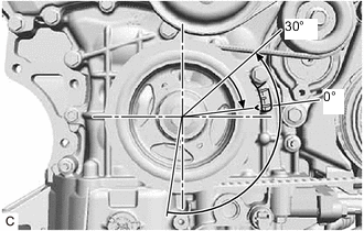
Turn the crankshaft counterclockwise 30° past the "0" timing mark, and then turn it clockwise to align the notch with the "0" timing mark.
-
Turn the crankshaft slightly to eliminate the slack in the chain sub-assembly.
Tech Tips
Make sure there is some slack in the chain sub-assembly around the area where the No. 1 chain tensioner assembly is installed.
-
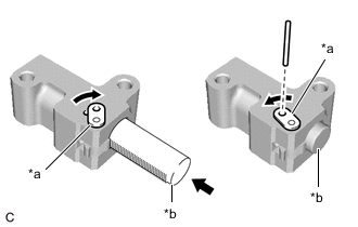
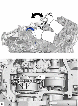
*a Stopper Plate *b Plunger Turn the stopper plate clockwise to release the lock, and push the plunger deep into the No. 1 chain tensioner assembly.
-
Turn the stopper plate counterclockwise to set the lock, and insert a 1.0 mm (0.0394 in.) diameter pin into the hole of the stopper plate.
-
Install the No. 1 chain tensioner assembly with the 2 bolts.
- Torque:
- 10 N*m { 102 kgf*cm, 7 ft.*lbf }
-
Remove the 1.0 mm (0.0394 in.) diameter pin from the No. 1 chain tensioner assembly.
-
-
INSPECT VALVE TIMING
-
Check the camshaft timing marks.
Note
-
Check each timing mark from a viewpoint directly in line with the center of the camshaft and the timing mark on each camshaft timing gear assembly and each camshaft timing exhaust gear assembly.
-
If the timing marks are checked from any other viewpoint, the valve timing may appear misaligned.
-
-
Check that each camshaft timing mark is positioned as shown in the illustration.
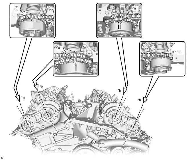
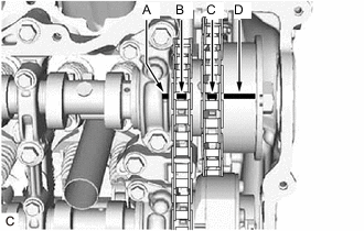
*a Timing Mark *b Viewpoint Tech Tips
For the camshaft or No. 3 camshaft sub-assembly:
Be sure to check mark (A) at the point where marks (B), (C) and (D) are positioned in line. If the marks are checked from any other viewpoint, they cannot be checked correctly.
-
If the valve timing is misaligned, reinstall the chain sub-assembly.
-
Turn the crankshaft 2 revolutions, set the No. 1 cylinder to TDC/compression and check the timing marks again.
-
-
INSTALL TIMING CHAIN COVER PLATE
-
INSTALL SPARK PLUG TUBE GASKET
-
INSTALL CYLINDER HEAD COVER SUB-ASSEMBLY LH
-
INSTALL CYLINDER HEAD COVER SUB-ASSEMBLY
-
INSTALL CAMSHAFT TIMING OIL CONTROL SOLENOID ASSEMBLY (for Intake Side of Bank 2)
-
INSTALL CAMSHAFT TIMING OIL CONTROL SOLENOID ASSEMBLY (for Exhaust Side of Bank 2)
-
INSTALL CAMSHAFT TIMING OIL CONTROL SOLENOID ASSEMBLY (for Exhaust Side of Bank 1)
-
INSTALL CAMSHAFT TIMING OIL CONTROL SOLENOID ASSEMBLY (for Intake Side of Bank 1)
-
INSTALL STUD BOLT
-
INSTALL RADIATOR PIPE CLAMP
-
INSTALL WIRE HARNESS CLAMP BRACKET
-
INSTALL ENGINE OIL LEVEL DIPSTICK GUIDE
-
INSTALL VACUUM PUMP ASSEMBLY
-
INSTALL IGNITION COIL ASSEMBLY
-
INSTALL ENGINE HANGERS
-
REMOVE ENGINE ASSEMBLY FROM ENGINE STAND