CYLINDER HEAD GASKET INSTALLATION
CAUTION / NOTICE / HINT
PROCEDURE
-
INSTALL CYLINDER HEAD GASKET
-
Clean the cylinder block sub-assembly and cylinder head sub-assembly with solvent.
-
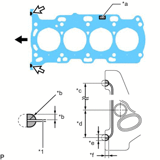
*1 Cylinder Head Gasket *a Lot No. *b 3.0 to 5.0 mm (0.118 to 0.197 in.) *c 152.5 mm (6.00 in.) *d 38 mm (1.50 in.) *e 7.0 to 9.0 mm (0.276 to 0.354 in.) *f 5.0 to 7.0 mm (0.197 to 0.276 in.) 
Front of Engine 
Seal Packing Apply seal packing to a new cylinder head gasket as shown in the illustration.
Note
-
Remove any oil from the contact surface.
-
Install the cylinder head gasket within 3 minutes and tighten the bolts within 15 minutes of applying seal packing.
-
-
Place the cylinder head gasket on the cylinder block sub-assembly as shown in the illustration.
Note
-
Remove any oil from the contact surfaces.
-
Pay attention to the installation direction.
-
Do not damage the cylinder head gasket.
-
-
-
INSTALL CYLINDER HEAD SUB-ASSEMBLY
Tech Tips
Perform "Inspection After Repair" after replacing the cylinder head sub-assembly.
-
Clean the cylinder head sub-assembly with solvent.
-
Place the cylinder head sub-assembly on the cylinder block sub-assembly.
Note
-
Check and clean the cylinder head set bolts and bolt holes.
-
Make sure that no oil is on the contact surface of the cylinder head sub-assembly.
-
Gently place the cylinder head sub-assembly in order not to damage the cylinder head gasket.
-
-
Apply a light coat of engine oil to the threads and under the heads of the cylinder head set bolts.
-
Install the 10 cylinder head set plate washers to the 10 cylinder head set bolts.
Note
-
Install the cylinder head set bolts to the same place they were removed from.
-
Be careful not to drop the cylinder head set plate washers into the cylinder head sub-assembly.
Tech Tips
The cylinder head set bolts are tightened in 3 progressive steps.
-
-
Step 1:
-
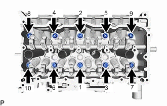
Using a 10 mm bi-hexagon socket wrench, install and uniformly tighten the 10 cylinder head set bolts in several steps in the order shown in the illustration.
- Torque:
- 85 N*m { 867 kgf*cm, 63 ft.*lbf }
-
-
Step 2:
-
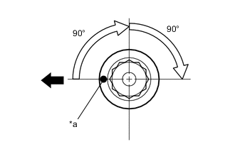
*a Paint Mark Front of Engine Mark the front of each cylinder head set bolt head with paint.
-
Tighten the cylinder head set bolts an additional 90°.
-
-
Step 3:
-
Tighten the cylinder head set bolts an additional 90°.
-
Check that the paint marks are now at a 180° angle to the front of the engine.
Note
After installing the cylinder head sub-assembly, wipe off any excess seal packing within 5 minutes.
-
-
-
INSTALL VALVE STEM CAP
-
INSTALL VALVE LASH ADJUSTER ASSEMBLY
-
INSTALL NO. 1 VALVE ROCKER ARM SUB-ASSEMBLY
-
CONNECT NO. 7 WATER BY-PASS HOSE
-
Connect the No. 7 water by-pass hose to the cylinder head sub-assembly and slide the clip to secure it.
-
-
INSTALL NO. 3 WATER BY-PASS PIPE
-
INSTALL CAMSHAFT HOUSING SUB-ASSEMBLY
-
INSTALL CAMSHAFT TIMING GEAR ASSEMBLY
-
INSTALL CAMSHAFT TIMING EXHAUST GEAR ASSEMBLY
-
ADD ENGINE OIL
-
INSTALL NO. 1 CHAIN VIBRATION DAMPER
-
INSTALL CHAIN SUB-ASSEMBLY
-
INSTALL CHAIN TENSIONER SLIPPER
-
INSTALL NO. 1 CHAIN TENSIONER ASSEMBLY
-
INSTALL TIMING CHAIN GUIDE
-
SET NO. 1 CYLINDER TO TDC/COMPRESSION
-
INSTALL ENGINE OIL LEVEL DIPSTICK GUIDE
-
INSTALL VACUUM PUMP ASSEMBLY
-
INSTALL TURBOCHARGER SUB-ASSEMBLY
-
CONNECT INLET TURBO OIL PIPE SUB-ASSEMBLY
-
INSTALL EXHAUST MANIFOLD CONVERTER SUB-ASSEMBLY (TWC: Front Catalyst)
-
INSTALL NO. 2 EXHAUST MANIFOLD HEAT INSULATOR
-
INSTALL NO. 1 EXHAUST MANIFOLD HEAT INSULATOR
-
INSTALL FUEL INJECTOR SEAL (for Direct Injection)
-
INSTALL DIRECT FUEL INJECTOR ASSEMBLY (for Direct Injection)
-
INSTALL FUEL DELIVERY PIPE SUB-ASSEMBLY (for Direct Injection)
-
CONNECT SENSOR WIRE (for Direct Injection)
-
INSTALL PORT FUEL INJECTOR ASSEMBLY (for Port Injection)
-
INSTALL FUEL DELIVERY PIPE (for Port Injection)
-
CONNECT NO. 6 ENGINE WIRE (for Port Injection)
-
INSTALL INTAKE MANIFOLD WITH INTERCOOLER ASSEMBLY AND THROTTLE WITH MOTOR BODY ASSEMBLY
-
CONNECT NO. 1 WATER BY-PASS HOSE AND NO. 2 WATER BY-PASS HOSE
-
INSTALL PURGE VALVE (PURGE VSV)
-
INSTALL TIMING CHAIN COVER ASSEMBLY