ADAPTIVE VARIABLE SUSPENSION SYSTEM, Diagnostic DTC:C1782
| DTC Code | DTC Name |
|---|---|
| C1782 | Power Source Voltage Malfunction |
DESCRIPTION
| DTC No. | Detection Item | DTC Detection Condition | Trouble Area | Warning Indicate | Note |
|---|---|---|---|---|---|
| C1782 | Power Source Voltage Malfunction | While the engine switch is on (IG), the voltage at terminal B is 10 V or less, or 16 V or more for 0.5 seconds. |
|
Does not come on | - |
WIRING DIAGRAM
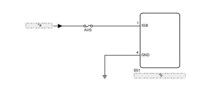
| *a | from IG Circuit |
| *b | Absorber Control ECU (Rear Acceleration Sensor) |
CAUTION / NOTICE / HINT
Note
-
Before performing troubleshooting, inspect the connectors of related circuits.
-
When the absorber control ECU (rear acceleration sensor) is replaced, switch to test mode and check that all test mode DTCs are cleared when their respective deletion conditions are met.
-
Before replacing the absorber control ECU (rear acceleration sensor), perform all of the following:
-
Symptom simulation.
-
DTC inspection.
-
GTS inspection.
-
If no malfunctions are found in other areas, replace the absorber control ECU (rear acceleration sensor).
-
Inspect the fuses for circuits related to this system before performing the following inspection procedure.
PROCEDURE
-
READ VALUE USING GTS (IG POWER SOURCE VOLTAGE)
-
Turn the engine switch off.
-
Connect the GTS to the DLC3.
-
Turn the engine switch on (IG).
-
Turn the GTS on.
-
Enter the following menus: Chassis / Air suspension / Data List.
Chassis > Air suspension > Data ListTester Display Measurement Item Range Normal Condition Diagnostic Note IG Power Source Voltage ECU power supply voltage Min.: 0.0 V
Max.: 25.5 V
11 to 14 V (Actual ECU power supply voltage): Engine switch on (IG) -
Chassis > Air suspension > Data ListTester Display IG Power Source Voltage OK The value is as specified in the normal condition column. Result Proceed to OK NG
NG 
INSPECT BATTERY Click here
OK 
-
-
CHECK FOR DTC
-
Clear the DTCs.
Chassis > Air suspension > Clear DTCs -
Turn the engine switch off.
-
Check for DTCs.
Chassis > Air suspension > Trouble CodesResult Result Proceed to DTC is not output A DTC is output B
A 
USE SIMULATION METHOD TO CHECK Click here
B
REPLACE ABSORBER CONTROL ECU (REAR ACCELERATION SENSOR) Click here
-
-
INSPECT BATTERY
-
Check the battery voltage.
Standard Voltage 11 to 14 V Result Proceed to OK NG
NG
CHECK OR REPLACE CHARGING SYSTEM OR BATTERY for 8AR-FTS: Click here
CHECK OR REPLACE CHARGING SYSTEM OR BATTERY for 2GR-FKS: Click hereOK
-
-
CHECK TERMINAL VOLTAGE (IGB)
-
Turn the engine switch off.
-
Disconnect the S51 absorber control ECU (rear acceleration sensor) connector.
-
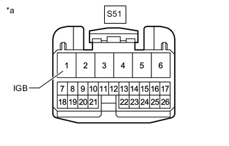
*a Front view of wire harness connector
(to Absorber control ECU (rear acceleration sensor))
Measure the voltage according to the value(s) in the table below.
Standard Voltage Tester Connection Switch Condition Specified Condition S51-1 (IGB) - Body ground Engine switch on (IG) 11 to 14 V Result Proceed to OK NG
NG
REPAIR OR REPLACE HARNESS OR CONNECTOR
OK
-
-
CHECK HARNESS AND CONNECTOR (GND TERMINAL)
-
Turn the engine switch off.
-
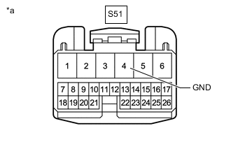
*a Front view of wire harness connector
(to Absorber control ECU (rear acceleration sensor))
Measure the resistance according to the value(s) in the table below.
Standard Resistance Tester Connection Condition Specified Condition S51-4 (GND) - Body ground Always Below 1 Ω Result Proceed to OK NG
OK
REPLACE ABSORBER CONTROL ECU (REAR ACCELERATION SENSOR) Click here
NG
REPAIR OR REPLACE HARNESS OR CONNECTOR
-