HEADLIGHT ASSEMBLY REASSEMBLY

CAUTION / NOTICE / HINT
Tech Tips
-
Use the same procedure for the RH side and LH side.
-
The procedure listed below is for the LH side.
PROCEDURE
-
PRECAUTION
Note
-
Handle components indoors as much as possible to prevent foreign matter from entering and adhering to headlight assembly components.
-
Do not reuse parts which have reduced fastening ability due to thread damage.
-
Do not touch the inner surface of the lens and metallic surfaces as much as possible, or they may become dirty.
-
Do not allow metallic surfaces to become dirty, as such surfaces become damaged even if they are only lightly wiped with a soft cloth.
-
When installing components, make sure that the wire harness is not pinched or pulled.
-
Do not use solvent to clean components. Only clean them with a dry cloth.
-
-
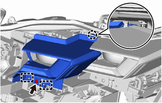
INSTALL HEADLIGHT FAN
-
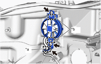
*a Clamp *b Guide Engage the guides to install the headlight fan with the 2 screws.
-
Connect the connector.
-
Engage the clamp.
-
-
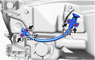
INSTALL HEADLIGHT LEVELING MOTOR
Note
-
Make sure to wear clean rubber gloves when performing this procedure.
-
Do not allow dirt or foreign matter to get on the headlight unit or other components.
-
If there are any fingerprints or foreign matter on the headlight unit or other components, wipe them off with a soft cloth.
-
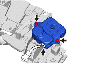
Install the headlight leveling motor with the 2 screws.
-
Connect the connector.
-
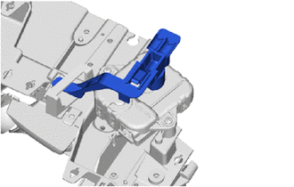
Install the spherical step.
-
-
INSTALL HEADLIGHT UNIT ASSEMBLY
Note
-
Make sure to wear clean rubber gloves when performing this procedure.
-
Do not allow dirt or foreign matter to get on the headlight unit assembly or other components.
-
If there are any fingerprints or foreign matter on the headlight unit assembly or other components, wipe them off with a soft cloth.
-
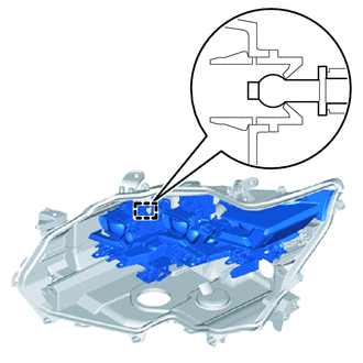
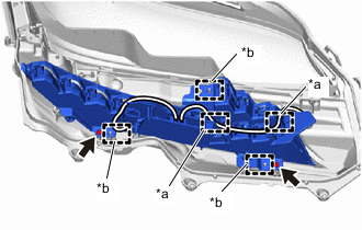
Engage the clamp to install the headlight unit assembly.
-
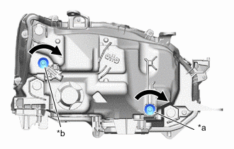
*a Vertical Aiming Screw *b Horizontal Aiming Screw 
Clockwise While holding the headlight unit assembly by hand, turn the vertical aiming screw and horizontal aiming screw as shown in the illustration to temporarily install it.
Tech Tips
Turn the aiming screw the same number of times as it was turned during removal.
-
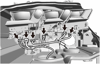
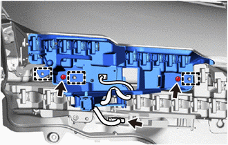
Connect the 6 connectors.
-
Engage the guides and claw to install the center lens bezel.
-
Install the screw.
-

Engage the guides and claw to install the center lens bezel.
-
Install the screw.
-
Engage the guide and claws to install the headlight unit bezel.
-
Install the 2 screws.
-
-
INSTALL CLEARANCE LIGHT UNIT
Note
-
Make sure to wear clean rubber gloves when performing this procedure.
-
Do not allow dirt or foreign matter to get on the headlight unit or other components.
-
If there are any fingerprints or foreign matter on the headlight unit or other components, wipe them off with a soft cloth.
-
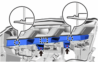
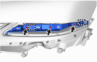
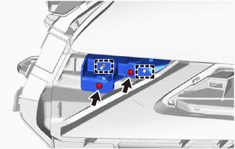
*a Wire Harness Guide *b Guide Engage the guides to install the clearance light unit.
-
Install the 2 screws.
-
Chck that the wire harness is securely installed to the wire harness guide as shown in the illustration.
-
-
INSTALL FRONT TURN SIGNAL LIGHT UNIT
Note
-
Make sure to wear clean rubber gloves when performing this procedure.
-
Do not allow dirt or foreign matter to get on the headlight unit or other components.
-
If there are any fingerprints or foreign matter on the headlight unit or other components, wipe them off with a soft cloth.
-
Engage the guides to install the front turn signal light unit.
-
Install the 2 screws.
-
Connect the connector.
-
-
INSTALL HEADLIGHT LENS GASKET
-

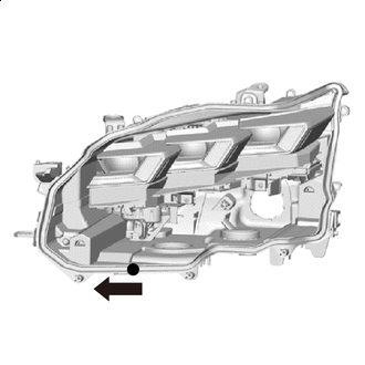
Cleaning Area Completely remove the old headlight lens gasket.
-
Clean the installation groove of the headlight lens.
-
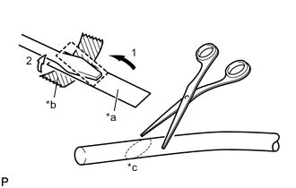
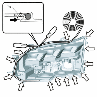
*a Release Paper *b Tape *c 45° Partially remove the release paper from a new headlight lens gasket, and cut off a piece of it.
-
Fold the release paper over the tip of a screwdriver and secure it in place with tape as indicated by the arrows, in the order shown in the illustration.
-
Using scissors, cut the end of the headlight lens gasket at a 45° angle.
-
Clockwise 
Starting Point Starting from the position shown in the illustration and moving counterclockwise, temporarily install the headlight lens gasket as shown in the illustration.
Note
Lightly set the gasket in place without pulling.
-
*a Peeling Paper Press 
Corner Groove 
Headlight Lens Gasket Using 2 screwdrivers with their tips wrapped in peeling paper, push the headlight lens gasket into the bottom of the groove.
-
Set the headlight lens gasket into the corner groove and using 2 screwdrivers with their tips wrapped in peeling paper, push the gasket into the bottom of the groove.
Note
-
Lightly set the gasket in place without pulling.
-
If the headlight lens gasket is set while pulled, the gasket will be pushed up at the corner groove.
-
-
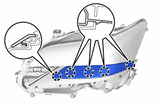
Repeat the following order while working in a circle back to the starting point: 1) Set headlight lens gasket into straight groove, 2) push into bottom of groove, 3) set into the corner groove and 4) push into bottom of groove.
-
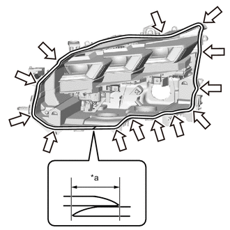
*a 20 mm (0.7874 in.) Corner Groove Using scissors, cut the headlight lens gasket at a 45° angle at the starting point so that the gasket overlaps itself 20 mm (0.7874 in.) or more and set the gasket in place.
-
Check the installation condition of the headlight lens gasket.
OK Gasket not pushed up or protruding. No gap where gasket overlaps. Note
Check the corners carefully since the gasket can easily become pushed up in those areas.
-
-
INSTALL HEADLIGHT LENS
Note
-
Make sure to wear clean rubber gloves when performing this procedure.
-
Do not allow dirt or foreign matter to get on the headlight lens or other components.
-
If there are any fingerprints or foreign matter on the headlight lens or other components, wipe them off with a soft cloth.
-
Clean the headlight lens gasket contact surface.
-
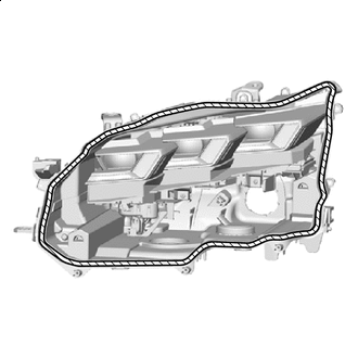
Set the headlight lens in place.
Note
Set the headlight lens in the middle of the headlight lens gasket as shown in the illustration.
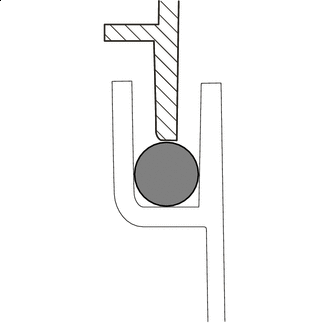
Headlight Lens Gasket 
Headlight Body Headlight Lens -
Check that the entire circumference of the headlight lens is positioned above the middle of the headlight lens gasket.
-
Engage the claws to install the headlight lens.
-
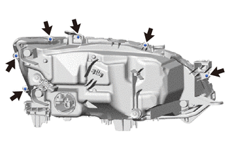
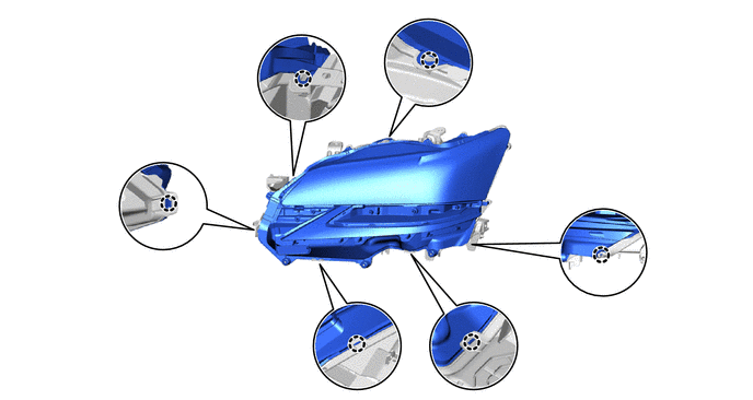
Install the 6 screws.
-
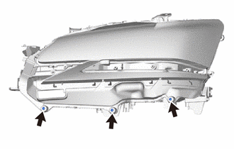
Using a T20H "TORX" screwdriver, install the 3 screws.
-
Connect the connector.
-
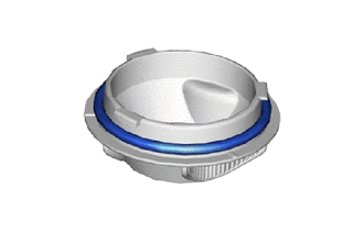
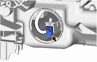
Install a new headlight socket cover gasket.
-
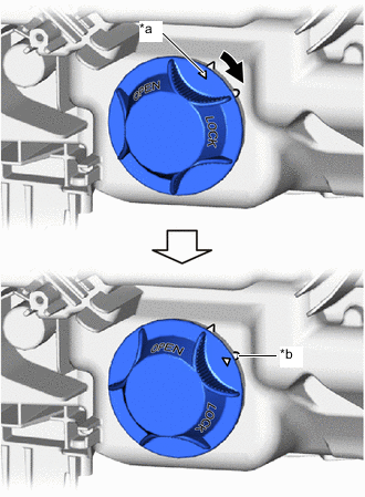
*a Matchmark *b Lock Position Mark Clockwise Align the matchmark of the headlight socket cover to the unlock position mark, and then rotate the headlight socket cover clockwise until the lock position mark to install the headlight socket cover.
-
Engage the guides to install the headlight aiming screw flexible extension.
-
Install the 4 screws.
-
-
INSTALL NO. 2 HEADLIGHT BRACKET
-
Engage the guides to install the No. 2 headlight bracket.
-
Install the 3 screws.
-
-
INSTALL NO. 1 HEADLIGHT BRACKET
-
Engage the guides to install the No. 1 headlight bracket.
-
Install the 2 screws.
-
-
INSTALL HEADLIGHT CONTROL COMPUTER ASSEMBLY
-
INSTALL HEADLIGHT LIGHT CONTROL ECU SUB-ASSEMBLY (w/ Adaptive High Beam System)
-
INSTALL HEADLIGHT COVER
-
Engage the claws to install the headlight cover.
-