HEADLIGHT ASSEMBLY DISASSEMBLY

CAUTION / NOTICE / HINT
The necessary procedures (adjustment, calibration, initialization, or registration) that must be performed after parts are removed, installed, or replaced during the headlight control computer assembly LH removal/installation are shown below.
| Replacement Part or Procedure | Necessary Procedure | Effect/Inoperative when not Performed | Link |
|---|---|---|---|
| Removal/installation of headlight control computer assembly LH |
|
Headlight leveling function | |
| Removal/installation of front bumper assembly | Adjust millimeter wave radar sensor assembly |
|
Tech Tips
-
Use the same procedure for the RH side and LH side.
-
The following procedure listed below is for LH side.
PROCEDURE
-
PRECAUTION
Note
-
Be sure to read Precaution thoroughly before servicing.
-
Handle components indoors as much as possible to prevent foreign matter from entering and adhering to headlight assembly components.
-
Do not reuse parts which have reduced fastening ability due to thread damage.
-
Do not touch the inner surface of the lens and metallic surfaces as much as possible, or they may become dirty.
-
Do not allow metallic surfaces to become dirty, as such surfaces become damaged even if they are only lightly wiped with a soft cloth.
-
When installing components, make sure that the wire harness is not pinched or pulled.
-
Do not use solvent to clean components. Only clean them with a dry cloth.
-
-
REMOVE HEADLIGHT COVER
-
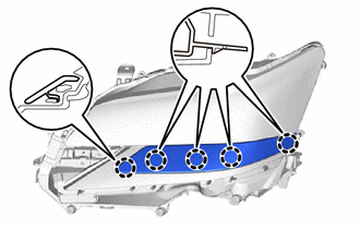
Disengage the claws to remove the headlight cover.
-
-
REMOVE HEADLIGHT LIGHT CONTROL ECU SUB-ASSEMBLY (w/ Adaptive High Beam System)
-
REMOVE HEADLIGHT CONTROL COMPUTER ASSEMBLY
-
REMOVE NO. 1 HEADLIGHT BRACKET
-
Remove the 2 screws.
-
Disengage the guides to remove the No. 1 headlight bracket.
-
-
REMOVE NO. 2 HEADLIGHT BRACKET
-
Remove the 3 screws.
-
Disengage the guides to remove the No. 2 headlight bracket.
-
-
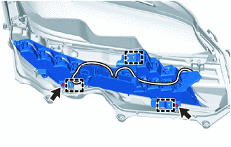
REMOVE HEADLIGHT LENS
Note
-
Make sure to wear clean rubber gloves when performing this procedure.
-
Do not allow dirt or foreign matter to get on the headlight lens or other components.
-
If there are any fingerprints or foreign matter on the headlight lens or other components, wipe them off with a soft cloth.
-
Remove the 4 screws.
-
Disengage the guides to remove the headlight aiming screw flexible extension.
-
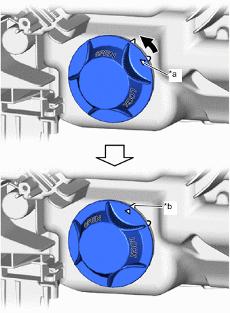
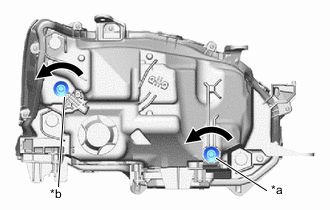
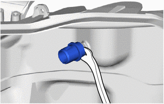
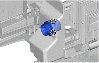
*a Matchmark *b Unlock Position Mark 
Counterclockwise Turn the headlight socket cover counterclockwise until the matchmark is aligned with the unlock position mark to remove the headlight socket cover.
-
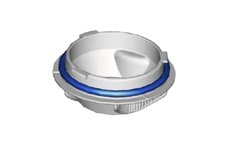
Remove the headlight socket cover gasket.
-
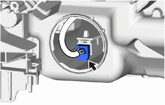
Disconnect the connector.
-
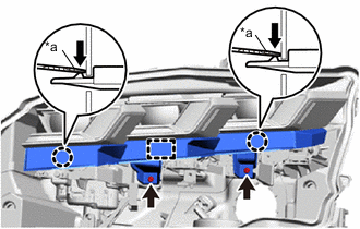
Using a T20H "TORX" screwdriver, remove the 3 screws.
-
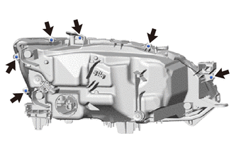
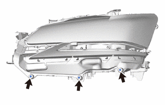
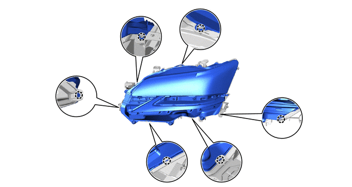
Remove the 6 screws.
-
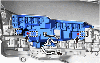
Disengage the claws.
-
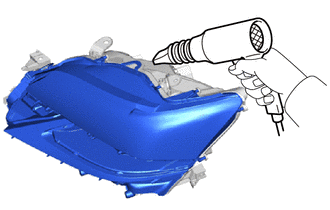
Using a dryer, heat the backside of the headlight assembly.
Note
If the headlight assembly is heated unevenly, it will deform or melt.
-
Remove the headlight lens.
Tech Tips
If the headlight lens cannot be removed even after heating, using a screwdriver with its tip wrapped with protective tape, lift the headlight lens. Be careful not to damage the headlight lens and housing.
-
-
REMOVE FRONT TURN SIGNAL LIGHT UNIT
Note
-
Prevention of static electricity is required during this procedure.
-
Use static electricity countermeasures SST (desktop antistatic mat set) and observe all precautions to prevent damage to the system by electrostatic discharge (ESD).
-
Make sure to wear clean rubber gloves when performing this procedure.
-
Do not allow dirt or foreign matter to get on the front turn signal light unit or other components.
-
If there are any fingerprints or foreign matter on the front turn signal light unit or other components, wipe them off with a soft cloth.
-
Do not use solvent to clean components. Only clean them with a dry cloth.
- SST
- 09890-47010 ( 09891-04010, 09891-04020, 09891-04030, 09891-04040 )
-
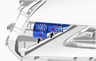
Disconnect the connector.
-
Remove the 2 screws.
-
Disengage the guides to remove the front turn signal light unit.
-
-
REMOVE CLEARANCE LIGHT UNIT
Note
-
Prevention of static electricity is required during this procedure.
-
Use static electricity countermeasures SST (desktop antistatic mat set) and observe all precautions to prevent damage to the system by electrostatic discharge (ESD).
-
Make sure to wear clean rubber gloves when performing this procedure.
-
Do not allow dirt or foreign matter to get on the clearance light unit or other components.
-
If there are any fingerprints or foreign matter on the clearance light unit or other components, wipe them off with a soft cloth.
-
Do not use solvent to clean components. Only clean them with a dry cloth.
- SST
- 09890-47010 ( 09891-04010, 09891-04020, 09891-04030, 09891-04040 )
-
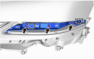
Remove the 2 screws.
-
Disengage the guides to remove the clearance light unit.
-
-
REMOVE HEADLIGHT LENS GASKET
-
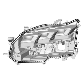

Headlight Lens Gasket Remove the headlight lens gasket.
Note
Make sure to replace the headlight lens gasket with a new one. Failure to do so may cause water ingress.
-
-
REMOVE HEADLIGHT UNIT ASSEMBLY
Note
-
Prevention of static electricity is required during this procedure.
-
Use static electricity countermeasures SST (desktop antistatic mat set) and observe all precautions to prevent damage to the system by electrostatic discharge (ESD).
-
Make sure to wear clean rubber gloves when performing this procedure.
-
Do not allow dirt or foreign matter to get on the headlight unit assembly or other components.
-
If there are any fingerprints or foreign matter on the headlight unit assembly or other components, wipe them off with a soft cloth.
-
Do not use solvent to clean components. Only clean them with a dry cloth.
- SST
- 09890-47010 ( 09891-04010, 09891-04020, 09891-04030, 09891-04040 )
Tech Tips
-
*a Vertical Aiming Screw *b Horizontal Aiming Screw Counterclockwise If the screwdriver connot be inserted and the claws cannot be disengaged, loosen the vertical aiming screw and horizontal aiming screw enough to allow the screwdriver to be inserted.
-
When loosen the vertical aiming screw and horizontal aiming screw, record the number of rotations of each screw.
-
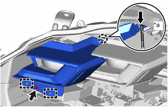
*a Protective Tape Push Remove the 2 screws.
-
Using a screwdriver with its tip wrapped in protective tape, disengage the claws and guide to remove the headlight unit bezel.
-
*a Protective Tape Push Remove the screw.
-
Using a screwdriver with its tip wrapped in protective tape, disengage the claw and guides to remove the inner lens bezel.
-
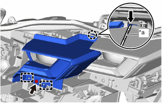
*a Protective Tape Push Remove the screw.
-
Using a screwdriver with its tip wrapped in protective tape, disengage the claw and guides to remove the center lens bezel.
-
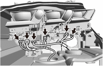
Disconnect the 6 connectors.
-
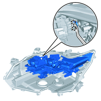
Using a clip remover, disengage the claws to separate the headlight unit assembly.
Tech Tips
Insert the clip remover between the headlight unit and pivot collar yo separate the headlight unit.
-
*a Vertical Aiming Screw *b Horizontal Aiming Screw Counterclockwise While holding the headlight unit assembly by hand, turn the vertical aiming screw and horizontal aiming screw as shown in the illustration until the headlight unit assembly can be removed.
Tech Tips
Make sure to remember the number of aiming screw rotations.
-
Using a clip remover, remove the pivot collar.
-
Engage the claws to install the pivot collar.
-
-
REMOVE HEADLIGHT LEVELING MOTOR
Note
-
Prevention of static electricity is required during this procedure.
-
Use static electricity countermeasures SST (desktop antistatic mat set) and observe all precautions to prevent damage to the system by electrostatic discharge (ESD).
-
Make sure to wear clean rubber gloves when performing this procedure.
-
Do not allow dirt or foreign matter to get on the headlight unit or other components.
-
If there are any fingerprints or foreign matter on the headlight unit or other components, wipe them off with a soft cloth.
-
Do not use solvent to clean components. Only clean them with a dry cloth.
- SST
- 09890-47010 ( 09891-04010, 09891-04020, 09891-04030, 09891-04040 )
-
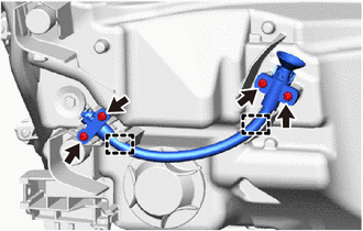
Remove the spherical step.
-
Disconnect the connector.
-
Remove the 2 screws and headlight leveling motor.
-
-
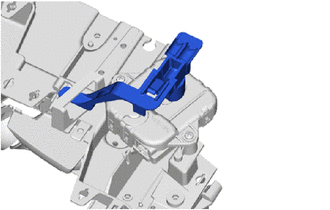
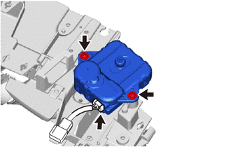
REMOVE HEADLIGHT FAN
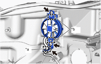
*a Clamp *b Guide
-
Disengage the clamp.
-
Disconnect the connector.
-
Remove the 2 screws.
-
Disengage the guides to remove the headlight fan.
-